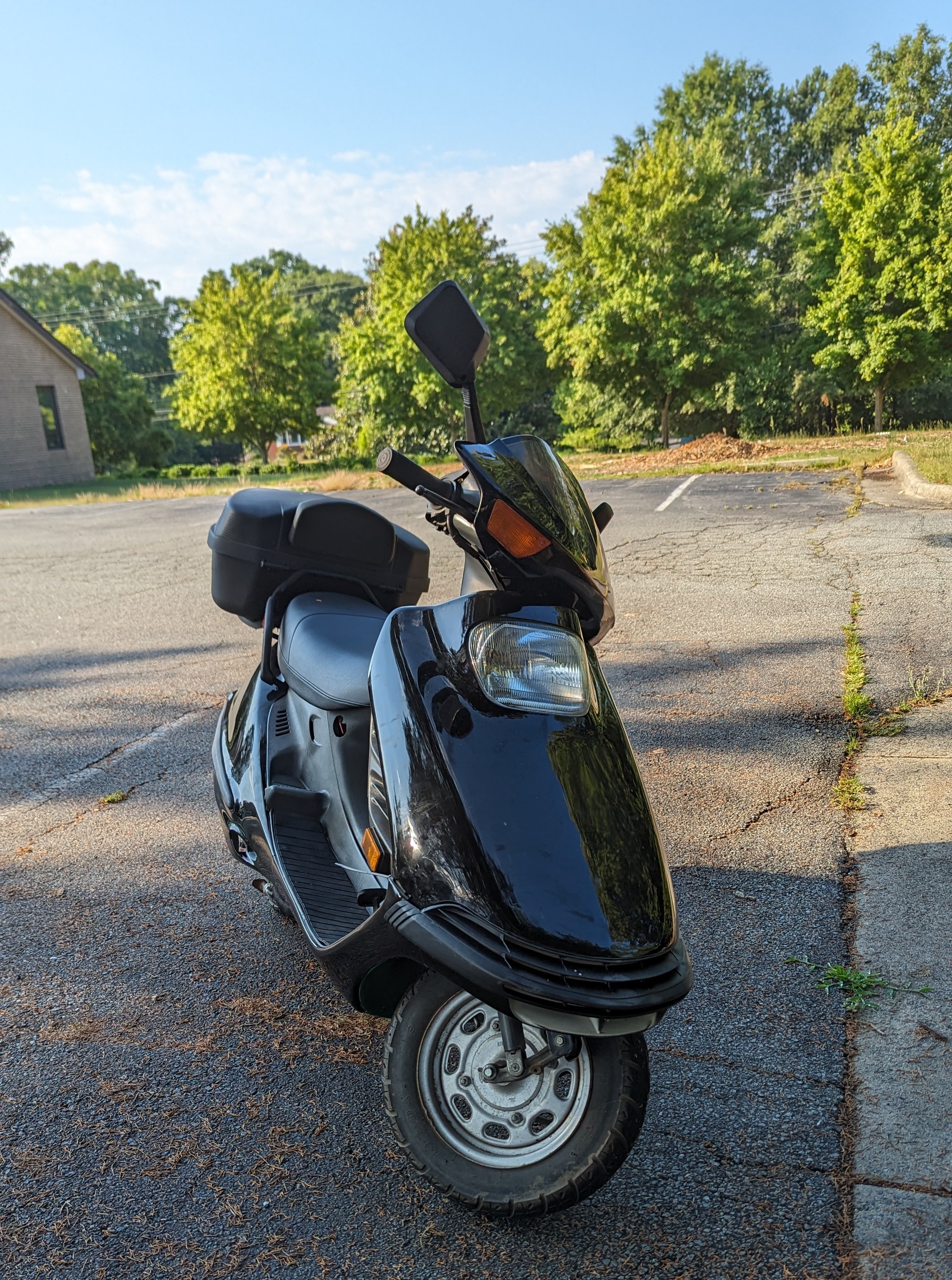
I have a 1987 Honda Elite 150 (CH 150) “Spacey” moped that I love to cruise around on. I struggled to find a service manual online. So I bought a copy on Ebay and scaned all of the pages. I then ran it through OCRmyPDF to make it easier to search. That PDF can be downloaded here. If you want the raw scanned pdf it can be downloaded here.
Hopefully by sharing it here I can help someone else.
Below is all of the OCR text from the service manual. The formatting is obviously terrible, but this should help others find this via Google.
 ‘IMPORTANT SAFETY NOTICE
Indicates a strong possibility of severe personal injury or loss of life if instructions are not followed.
CAUTION: Indicates a possibility of personal injury or equipment damage if instructions are not followed. NOTE: Gives helpful information.
Detailed descriptions of standard workshop procedures, safety principles and service operations are not included. It is important to note that this manual contains some warnings and cautions against some specific service methods which could cause PERSONAL INJURY to service personnel or could damagea vehicle or render it unsafe. Please understnad that those warnings could not cover all conceivable ways in which service, whether or not recommended by Honda might be done or of the possibly hazardous consequences of each conceivable way, nor could Honda investigate all such ways. Anyone using service procedures or tools, whether or not recommended by Honda must satisfy himself thoroughly that neither personal safety nor vehicle safety will be jeopardized by the service methods or tools selected.

 HOW TO USE THIS MANUAL
Follow the Maintenance Schedule (Section 3) recommendations to ensure that the scooter is in peak operating condition and the emis- sion levels are within the standards set by the U.S. Environmental Protection Agency and the California Air Resources Board. Perform- ing the first scheduled maintenance is very important. It compensates for the initial wear that occurs during the break-in period.
Sections 1 through 3 apply to the whole scooter, while sections 4 through 17 describe parts of the scooter, grouped according to lo- cation.
Find the section you want on this page, then turn to the table of contents on page 1 of that section.
Most sections start with an assembly or system illustration, service information and troubleshooting for the section. The subse- quent pages give detailed procedures.
If you don’t know the source of the trouble, go to section 18, TROUBLESHOOTING.
All information, illustration, directions and specifi- ;.
ae a
cations included in this publication are based on
the latest product information available at the time of approval for printing. HONDA MOTOR CO., LTD. reserves the right to make changes at any time without notice and without incurring any obligation whatever. No part of this publication may be reproduced without written permission. .
HONDA MOTOR CO., LTD. Service Publications Office
CONTENTS GENERAL INFORMATION
|
LUBRICATION
|
eal, ee
Date of Issue: November, 1986 © HONDA MOTOR CO., LTD.
|
|
|
|
ENGINE
MAINTENANCE 3 FUEL SYSTEM
ENGINE REMOVAL/INSTALLATION
f
CYLINDERHEAD/VALVES Eg
a ae
z) }10
os ae
ELECTRICAL EQUIPMENT WIRING DIAGRAM
TROUBLESHOOTING INDEX
~
CYLINDER/PISTON
DRIVE PULLEY/CLUTCH/DRIVEN PULLEY
FINAL REDUCTION ALTERNATOR/STARTER CLUTCH
CRANKCASE/CRANKSHAFT
COOLING SYSTEM FRAME COVERS
STEERING/FRONTWHEEL/BRAKE/ SUSPENSION
;
CHASIS REAR WHEEL/BRAKE/SUSPENSION


 GENERAL SAFETY
1-1 TOOLS 1-7 SERVICE RULES
1-1 CABLE & HARNESS ROUTING 1-8 MODEL IDENTIFICATION
1-2 EMISSION CONTROL SYSTEM 1-12 SPECIFICATIONS
1-3 EMISSION CONTROL INFORMATION
LABEL 1-14 TORQUE VALUES 1-5
GENERAL SAFETY
If the engine must be running to do some work, make sure the area is well-ventilated. Never run the engine in a closed area. The exhaust contains poisonous carbon monoxide gas that may cause loss of consciousness and lead death.
Gasoline is extremelyflammable and is explosive under certain conditions. Do not smoke or allow flames or sparks in your working area.
SERVICE RULES
The battery electrolyte contains sulfuric acid. Protect your eyes, skin and clothing. In case of contact, flush thoroughly with water and call a doctor if electrolyte gets in your eyes.
The battery generates hydrogen gas which can be highly explo- sive. Do not smoke or allow flames or sparks near the battery, especially while charging it.
1, Use genuine Honda or Honda-recommended parts and lubricants or their equivalents. Parts that do not meet Honda’ design specifications may damage the scooter.
2. Use the special tools designed for this product.
3. Use only metric tools when servicing this scooter. Metric bolts, nuts, and screws are not interchangeable with English fas-
teners. The use of incorrect tools and fasteners may damage the scooter.
. Install new gaskets. O-rings, cotter pins, lock plates, etc. when reassembling.
of.
When tightening a senies of bolts or nuts, begin with larger-diameter or inner bolts first, and tighten to the specified torque diagonally, unless a particular sequence is specified.
[ep] .
Clean parts in cleaning solvent upon disassembly. Lubricate any sliding surfaces before reassembly.
.
After reassembly, check all parts for proper installation and operation.
[8]
Route all electrical wires as shown beginning on page 1-7, Cable & Harness Routing.
1. GENERAL INFORMATION
1-1

 GENERAL INFORMATION MODEL IDENTIFICATION
(1) CARBURETOR IDENTIFICATION NUMBER _
The carburetor identification number is stamped on the right side of the carburetor.
—| The color label is attached to the fuel tank below the seat.
1-2
The VIN (Vehicle Identification Number) is attached to the left side of the inner box.
The engine serial number is stamped on the back of the crankcase near the rear wheel. :

 ZL
a
Z
_
SPECIFICATIONS
DIMENSIONS
FRAME
ITEM
Overall length Overall width Overall height Wheel base Ground clearance Dry weight
Type
Front suspension, travel Rear suspension, travel Maximum weight capacity Front tire size
Rear tire size
Front tire pressure
Rear tire pressure
Front brake Rear brake Fuel capacity Caster angle Trail length
Type
Cylinder arrangement Bore and stroke Displacement Compression ratio Engine oil capacity
Lubrication system Coolant capacity
Air filtration
Cylinder compression
SPECIFICATION
y) =
3 =
1,880 mm (74.0 in) 665 mm (26.2 in) 1,140 mm (44.9 in) 1,255 mm (49.4 in) 125 mm (4.9 in) 105 kg (232 Ib)
ENGINE
Back bone
Bottom link 75 mm (3.0 in)
Power unit swingarm 96 mm (3.8 in)
159 kg (338 Ibs)
3.50—10 —4PR, tubeless
3.50—10 —4PR, tubeless
150 kPa (1.5 kg/cm?, 21 psi)
200 kPa (2.0 kg/cm?, 28 psi) Up to 90 kg (200 Ibs) load 250 kPa (2.5 kg/cm2, 36 psi) Up to vehicle capacity load Internal expanding shoes
Internal expanding shoes
8.0 liters (2.1 Us gal, 1.8 Imp gal)
27° OO’
84 mm (3.3 in)
Water cooled 4-stroke, OHC engine Single cylinder
58.0 x 57.8 mm (2.283 x 2.275 in) 153 cm? (9.3 cu in)
10.0: 1
1.34 liter (1.42 Us qt, 1.18 Imp qt) at disassembly 0.8 liter (0.8 US qt, 0.7 Imt qt) at draining
Forced pressure and wet sump
1.0 liters (1.1 US qt, 0.9 Imp qt)
Paper filter
1,300 kPa (13.0 kg/cm2, 184 psi)
Intake valve
Exhaust valve
Opens Closes Opens closes
0° (BTDC) 30° (ABDC) 35° (BBDC)
at 1.1 mm lift
Valve clearance (Cold) Engine weight
Idle speed
0° (ATDC)
IN/EX: 0.1 mm (0.004 in) 27.3 kg (60.20 Ib)
1,500 + 100 rpm
GENERAL INFORMATION
1-3

 GENERAL INFORMATION ITEM
SPECIFICATION
VEO3C (VEOA4C, California model) 18.5 mm (0.73 in)
See page 4-11
#102 (#98, High altitude type) #35
Automatic centrifugal clutch, dry type 2.2—0.9
7.318: 1
Condenser capacitive discharge ignition (CDI) Starting motor
12V—203 W/ 5,000 rpm
(ND) X22EPR-U9,X20EPR-U9
(NGK) DPR7EA-9, DPR6EA-9 0.8—0.9 mm (0.032—0.035 in) 10° BTDC/ 2,100 rpm
27° BTDC/ 4,000 rpm
12 V9 AH
20 A (Main)
10 A (Stop/taillight, License light, Position light, Turn signal relay)
10 A (Front stop switch, Rear stop light switch, Instru- ment, Horn)
10 A (Starter switch)
CARBURETION
DRIVE TRAIN
ELECTRICAL
Identification number Float level
Pilot screw initial opening Main jet
LIGHTS
Headlight, Low/High
Brake/Tail light
Turn signal/Position light (front)
(rear)
5 A (Fan motor)
12 V—55/60 W
12 V—21/5W
12 V—21/5W
12 V—21 W
12 V—3W.x43 (2 cp) 12 V—3.4 W x 2 (2 cp) 12 V—3.4 W (2 cp)
12 V—8 W (2 cp)
1-4
Slow jet
Clutch type Primary reduction Final reduction
Ignition Starting system Alternator Spark plug
Spark plug gap Ignition timing
Battery capacity Fuse capacity
"EF mark full advance
Instrument light
Turn signal indicator light High beam indicator License plate light
SEA No. 1157 SEA No. 1034 SAE No. 1073 SAE No. 158 SAE No. 158 SAE No. 158

 TORQUE VALUES ENGINE
|
TEM
Oil bolt
Oil bolt
Cylinder head cap nut
“ater pump impeller
Cylinder head cover bolt
Ol filter screen cap
Cam chain tensioner sealing bolt Cam chain tensioner bolt
Clutch drive plate nut
Flywheel nut
Crankcase bolt
Drive face seal cover bolt
Drive face nut
Clutch outer nut
Transmission case cover bolt Starter clutch socket bolt Transmission oil level check bolt
Q’TY THREAD DIA. (mm) |
1 12
2 8
4 8
1 8
5 6
1 36
1 8
2 8
1: 28
1 14
7 6
3 4
1 12
1 10 | 7 6| 3 6
1 10
O’TY THREAD DIA. (mm)
1 8
1 10
1 10
1 10
1 12
1 14
4 8
2 8
1 25.4 1 25.4 1 25.4
2 8 Z 8 2 8 2 8
1 8 1 8 2 6 2 8 6 8 1 5 4 8 2 7
TORQUE Nem (kg-m, ft-lb)
18—22 (1.8—2.2, 13—16) 8—12 (0.8—1.2, 6—9)
20—24 (2.0—2.4, 14—17) 10—14 (1.0—1.4, 7—10)
8—12 (0.8—1.2, 6—9) 19—25 (1.9—2.5, 14—18)
8—12 (0.8—1.2, 6—9) 12—16 (1.2—1.6, 9—12) 50—60 (5.0—6.0, 36—43) 50—60 (5.0—6.0, 36—43)
8—12 (0.8—1.2, 6—9) 3—5 (0.3—0.5, 2.2—3.6)
50—60 (5.0—6.0, 36—43) 35—45 (3.5—4.5, 25—32) 10—14 (1.0—1.4, 7—10) 10—14 (1.0—1.4, 7—10) 10—15 (1.0—1.5, 7—11)
TORQUE Nem (kg-m, ft-lb)
18—22 (1.8— 2: 2, 13—16) 40—50 (4.0—5.0, 29—36) 40—50 (4.0—5.0, 29—36) 35—45 (3.5—4.5, 25—32) 50—70 (5.0—7.0, 36—51) 100—120 (10.0—12.0, 72—87) 24—30 (2.4—3.0, 17—22) 15—25 (1.5—2.5, 11—18)
2—3 (0.2—0.3, 1.4—22) 120—150 (12.0—15.0, 87—108)
5—13 (0.5—1.3, 4—10)
0.8—1.2 (0.08—0.12, 0.6—0.9 15—20 (1.5—2.0, 11—14 24—30 (2.4—3.0, 17—22 15—25 (1.5—2.5, 11-18
27—33 (2.7—3.3, 20—24 27—33 (2.7—3.3, 20—24 8—12 (0.8—1.2, 6—9)
24—30 (2.4—3.0, 17—22) 28—32 (2.8—3.2, 20—23)
1.5—3 (0.15—0.3, 1.1—2.2) 32—38 (3.2—3.8, 23—27) 27—33 (2.7—3.3, 20—24)
REMARKS
Left hand threads
Apply a locking agent
REMARKS
Apply oil Apply oil
Apply locking agent
Apply locking agent
Apply oil
FRAME
ITEM
Engine hanger stopper nut Engine hanger bracket mut Engine hanger bolt
Engine mounting bolt
Front axle nut
Rear axle nut
Rear shock absorber mount bolt
Sear shock absorber damper lock nut| 799 cone race
Steering stem nut
Sneering stem lock nut Senet shock absorber:
—lower bolt
—lower nut
—wpper mount bolt
—Gamper lock nut Se ire o>
mrake panel side mt fork side
See acm pot Peat ar pot Wes Tum Tr
Spescumet=sr came se Exhaust mufSer 2ot Exhaust poe gpet Tur
="
Torque Spec cet ‘ete steve are for most of the tightening points. If a specificationis not listed, follow the standard torque values Delins
GENERAL INFORMATION

 GENERAL INFORMATION STANDARD TORQUE VALUES
TYPE
5 mm bolt, nut 6 mm bolt, nut 8 mm bolt, nut
10 mm bolt, nut 12 mm bolt, nut
TORQUE Nem (kg-m, ft-lb)
4.5—6.0 (0.45—0.6, 3.3—4.3) 8—12 (0.8—1.2, 6—9)
18—25 (1.8—2.5, 13—18) 30—40 (3.0—4.0, 22—29) 50—60 (5.0—6.0, 36—43)
TYPE
5 mm screw
6 mm screw, and 6 mm bolt with 8 mm head
6 mm flange bolt, nut
8 mm flange bolt, nut
10 mm flange bolt, nut
TORQUE Nem (kg-m, ft-lb)
3.5—5 (0.35—0.5, 2.5—3.6) 7—11 (0.7—1.1, 5—8)
10—14 (1.0—1.4, 7—10) 24—30 (2.4—3.0, 17—22) 35—45 (3.5—4.5, 25—32)

 o@it]bfK|© Ae)=oOa
= teering stem wrench
Ss hatt protector Pe
available in U.S.A. 07916—GKOO000 —- Adjustable pin spanner
Fiywheel puller
Bearing remover, 12 mm
(Spindle assy, 12 mm)
(Remover weight)
Bearing remover handle
Bearing remover, 17 mm
Remover weight
Valve guide driver, 5.0 mm
Attachment 07945—3330300
Remover weight
Remover weight
TOOL NUMBER
A937X—041 — XXXXX 07631—0010000
07GMA—KS40100 07916—1870101
ALTERNATE TOOL
Vacuum pump (U.S.A. only) Pressure pump (U.S.A. only) Equivalent commercially available in U.S.A.
Equivalent commercially
TOOL NUMBER
ST-AH-260-MC7 4 ST-AH-255-MC7 4
07916—KM10000 07702—0020001
07936—3710200
07936—3710200
REF. SECT.
07931—1870000 07933—KG20000 07936— 1660001 (07936— 1660100) (07741 —0010201) 07936—3710100 07936—3710300 07741—0010201 07942—MA60000
Vater seal driver
07945—4150400
Water seal driver (U.S.A. only)
GN-AH-065—415
aring driver
07945—GC80000
oOo race remover
07946—GA70000 Race remover
07946—3710400 Ww©wutch spring compressor
07960—KM10000
Spring compressor attachment
07960—KM10100 | 8 Spring compressor (bolt)
07960—KJ90000
|8 Seal and case assembly tool
07965— 1480010
9 As i
(07965—1480100)
9 As
(07965—GMO00300)
9 Spring holder attachment
07967—1150100
15 Rear shock absorber attachment |07967—GA70102
14
Shock absorber attachment 2ive guide reamer, 5.0 mm
~’MON
DESCRIPTION
07967—KM10100 07984—MA60000
TOOL NUMBER
ALTERNATE TOOL
TOOL NUMBER
|
14 6
REF SECT
4 14
Fat eee sauce
07401—0010000
tock get erench. 30 x 32 mm 07716—0020400 _ | Equivalent commercially available in U.S.A. Secerssart
07716—0020500 ‘| Equivalent commercially
|
14
8 10
8,9, 14 9
9, 14 14
9,14 15
9 8,9 14 14
6
6 14,15
Umer Tome Pyete Toce
Attachmese, 32 = 35 eum Attachment, 37 = 42D com Attachment, 42 = 47 aun Attachment, 52 = 55 eum Pilot1,2 mm
Pilot, 15 mm
Pilot, 17 mm
Pilot, 20 mm
Bearing remover shaft
Bearing remover head, 12 mr Driver
Valve guide driver
Valve spring compressor Shock absorber compressor
available in U.S.A.
07725—0030000
07725—0040000 |Band strap wrench commer-
cially available in U.S.A.
07746—0010100 07746—0010200 07746—0010300 07746—0010400 97746—0040200 07746 —0040300 o7746—
O77465—
27728 —
0050700 — Equivalent commercially 07746—0050300 —lavailable in U.S.A. 07743—0010000
07743—0020000
07757—0010000
|
07959—3290001
|
GENERAL INFORMATION

 GENERAL INFORMATION
CABLE & HARNESS ROUTING
Note the following when routing cables and wire harnesses:
@ A loose wire, harness or cable can be safety hazard. After clamping, check each wire to be sure it is secure.
@ Do not squeeze wires against the weld or its clamp.
® Secure wires and wire harnesses to the frame with their te- spective wire bands at the designated locations. Tighten the bands so that only the insulated surfaces contact the wires or wire harnesses.
@ Route harnesses so they are neither pulled tight nor have excessive slack.
® Protect wires and harnesses with electrical tape or tube if they contact a sharp edge or corner.
Clean the attaching surface thoroughly before applying tape.
@ Do not use a wire or harness with a broken insulator. Repair by wrapping them with protective tape or replace them.
@ Route wire harnesses to avoid sharp edges or corners.
@ Avoid the projected ends of bolts and screws.
@ Keep wire harnesses away from the exhaust pipes and other hot parts.
® Be sure grommets are seated in their grooves properly.
@ After clamping, check each harness to be certain that it is not interfering with any moving or sliding parts.
@ After routing, check that the wire harnesses are not twisted or kinked.
@ Wire harnesses routed along the handlebars should not be pulled taut, have excessive slack, be pinched by or interfere with adjacent or surrounding parts in all steering positions.
@ After routing, check that the wire harnesses are not twisted or kinked.
®@ Do not bend or twist control cables. Damaged control cables will not operate smoothly and may stick or bind.
1-8

 (7) THERMOSENSOR WIRE
(3) THROTTLE CABLE /
(4) WIRE HARNESS
(5) BRAKE LOCK CABLE
(6) FUSE BOX
(8) RESERVE TANK
GENERAL INFORMATION
(2) FRONT BRAKE CABLE
1-9

 GENERAL INFORMATION
1-10
(7) POSITIVE (+) CABLE
(5) BATTERY
(6) NEGATIVE (-) CABLE
(3) WATER HOSE
(8) WATER HOSE

 ,© . ©@
(4) IGNITION COIL
(1) STARTER RELAY
(3) WIRE HARNESS
(2) CDI UNIT
GENERAL INFORMATION
1-11

 GENERAL INFORMATION
EMISSION CONTROL SYSTEMS
The U.S. Environmental Protection Agency and California Air Resources Board (CARB) require manufactures to certify that their motor scooters comply with applicable exhaust emissions standards during their useful life, when operated and main- tained according to the instructions provided, and that motor scooters built after January 1, 1983 comply with applicable noise emission standards for one year or 6,000 km (3,730 miles) after the time of sale to the ultimate purchaser, when oper- ated and maintained according to the instructions provided. Compliance with the terms of the Distributor’s Warranty for Honda Motor Scooter Emission Control Systems is necessary in order to keep the emissions system warranty in effect.
SOURCE OF EMISSIONS
The combustion process produces carbon monoxide and hydrocarbons. Control of hydrocarbons is very important because, under certain conditions, they react to form photochemical smog when subjected to sunlight. Carbon monoxide does not react in the same way, but it is toxic.
Honda Motor Co., Ltd. utilizes lean carburetor settings as well as other systems, to reduce carbon monoxide and hydro- carbons.
EXHAUST EMISSION CONTROL SYSTEM
The exhaust emission control system is composed of a lean carburetor setting, and no adjustments should be made except the idle speed adjustment with the throttle stop screw.
CRANKCASE EMISSION CONTROL SYSTEM
The engine is equipped with a closed crankcase system which routes crankcase emissions through the air cleaner and into the combustion chamber. Condensed crankcase vapors are accumulated in a storage tank which must be emptied periodically. See the Maintenance Schedule in section 3.
(1) AIR CLEANER
Uf/—“—=> [Gan
(6)BREATHERne SEPARATOR
(5) DRAIN TUBE
1-12
(4) DRAIN PLUG
(3) BREATHER CHAMBER
(2) CARBURETOR
<4 <—
(7) FRESH AIR
(8) BLOWBY GAS
le

 Zz
This mode! complies with California Air Resources Board requirements for evaporative emission regulations.
we! vapor from the fuel tank is routed into a charcoal canister where it is adsorbed and stored while the engine is stopped. When the engine is running and the purge control diaphragm valve is open, fuel vapor in the charcoal canister is drawn into
| > é
I (4)AIRCLEANER
EVAPORATIVE EMISSION CONTROL SYSTEM (California model only)
h
gine through the carburetor.
(1) CHARCOAL CANISTER
(7)FRESHAIR [> = foe
(6) DRAIN
NOISE EMISSION CONTROL SYSTEM
(5) CARBURETOR
TAMPERING WITH THE NOISE CONTROL SYSTEM IS PROHIBITED: Federal law prohibits the following acts or the causing thereof: (1) The removal or rendering inoperative by any person, other than for purposes of maintenance, repair or replace- ment, of any device or element of design incorporated into any new vehicle for the purpose of noise control prior to its sale or delivery to the ultimate purchaser or while it is in use; or (2) the use of the vehicle after such device or element of design has been removed or rendered inoperative by any person.
; eo AMONGTHOSEACTSPRESUMEDTOCONSTITUTETAMPERINGARETHEACTSLISTEDBELOW:
1. Removal of, or puncturing the muffler, baffles, header pipes or any other component which conducts exhaust gases. 2. Removal of, or puncturing of any part of the intake system.
3. Lack of proper maintenance.
4. Replacing any moving parts of the vehicle, or parts of the exhaust or intake system, with parts other than those specified by the manufacturer.
GENERAL INFORMATION
(3) PURGE CONTROL VALVE
/
<<(8)FRESHAIR
A (9) FUEL VAPOR &
1-13

 GENERAL INFORMATION
EMISSION CONTROL INFORMATION LABEL
An Emission Control Information Label is located on the fuel tank as shown. It contains basic tune-up specifications. &
(1) EMISSION INFORMATION LABEL
es
EMISSION CONTROL INFORMATION UPDATE LABEL
After making a high altitude carburetor adjustment (page 4-12), attach a vehicle emission control information update label on the fuel tank as shown.
Instructions for obtaining the update label are given in Service Letter No. 132.
VACUUM HOSE ROUTING DIAGRAM LABEL (California model only) ~ The Vacuum Hose Routing Diagram Label is attached to the fuel tank. Route the vacuum hoses as shown on this label.
(vacuum HOSE ROUTING DIAGRAM »
1-14
ae
IN. MANIFOLD
Kv7—760_/
(2) VACUUM HOSE ROUTING DIAGRAM LABEL
ENGINE FAMILY —HHNO15341A8
(CH150)
,
EVAPORATIVE FAMILY — 87XA
FUEL CALIFORNIA VEHICLE TANK
SLOW.
AIR CUT VALVE
FRONT OF VEHICLE

 6 u® uU®s
U®
MEMO
.o
.@

 LUBRICATION
2-0
(3) OIL PUMP
(1) OIL PIPE
(2) OIL FILTER SCREEN

 u®@
u®
u ®@
SERVICE INFORMATION
2-1 OIL PUMP INSPECTION TROUBLESHOOTING
2-1 OILPUMP ASSEMBLY ENGINE OIL
2-2. OILPUMP INSTALLATION ENGINE OIL FILTER SCREEN CLEANING
2-2 TRANSMISSION OIL
OIL PUMP REMOVAL
2-2 LUBRICATION POINTS OIL PUMP DISASSEMBLY 2-3
2-3 2-4 2-5 2-6 2-7
SERVICE INFORMATION
GENERAL
®@ This section covers maintenance of the oil pump, engine oil and transmission oil.
SPECIFICATIONS Engine oil capacity Transmission oil
Recommended oil
1.0 liter (1.1 US qt, 0.9 Imp qt) at disassembly 0.8 liter (0.8 US qt, 0.7 Imp qt) at change
0.18 liter (0.19 US qt, 0.16 Imp qt) at disassem- bly
0.15 liter (0.16 US qt, 0.13 Imp qt) at change
Use Honda 4-Stroke Oil or equivalent. API Service Classification: SE or SF VISCOSITY: SAE 10W—40
OIL VISCOSITES
SAE 20W-50
SAE 20W 40 SAE 10W 40
SAE 10W 30
Oil pump
TORQUE VALUES
Oil filter screen cap
Transmission oil drain bolt Transmission oi! level check bolt Oil pump mounting bolt
TROUBLESHOOTING
Oil Level Too Low
* External oil leaks.
e Worn valve guide or seal. e Worn piston rings.
Oil Contamination
¢ Oil not changed often enough. e Head gasket faulty
e Worn piston rings.
Poor Lubrication Pressure
¢ Oil level too low.
2 Clogged oil filter, oil passage, and/or oil pipe. ¢ Faulty oil pump.
Other viscosities shown in the chart may be used
(e) 20
40 60 80 when the average temperature in your riding area
‘:;;;; iswithintheindicatedrange. eo
8
100 °F an
mm (in)
ITEM
Rotor tip clearance Body clearance Rotor end clearance
STANDARD
0.15 (0.006) 0.15—0.20 (0.006—0.008)
0.04—0.09 (0.002—0.004)
19—25 Nem (1.9—2.5 kg-m, 14—18 ft-lb) 10—14 Nem (1.0—1.4 kg-m, 7—10 ft-lb) 10—15 Nem (1.0—1.5 kg-m, 7—11 ft-lb) 8—12 Nem (0.8—1.2 kg-m, 6—9Q ft-lb)
SERVICE LIMIT
0.20 (0.008) 0.25 (0.010) 0.12 (0.005)
2. LUBRICATION

 LUBRICATION
OIL LEVEL
Stop the engine and support the scooter upright on level ground.
Check the oil level with the filler cap/dipstick
Do not screw in the dipstick when making this check
If the level is near the lower level, fill to the upper level with the recommended engine oil (page 2-1).
OIL CHANGE
NOTE
e Drain the oil from the crankcase while the engine is warm. This ensures complete and rapid draining.
Place an oil pan under the engine, and remove the oil filter screen cap.
After the oil has been completely drained, be sure the O-ring is in good condition and install the filter, spring and cap.
TORQUE: 19—25 Nem (1.9—2.5 kg-m, 14—18 ft-lb)
Pour the recommended oil (page 2-1) through the oil filler hole.
ENGINE OIL CAPACITY:
0.8 liter (0.8 US qt, 0.7 Imp qt) at oil change
Reset the indicator by inserting the key in the indicator slot below the instrument panel.
Reinstall the oil filler cap. Start the engine and let it idle for few minutes.
Stop the engine and recheck the oil level.
Check that there are no oil leaks.
ENGINE OIL FILTER SCREEN CLEANING
Drain the engine oil.
Remove the oil filter screen and spring.
Clean the oil filter screen.
Make sure that the O-ring is in good condition. Install the oil filter screen and spring.
Install the filter screen cap.
TORQUE:19—25N-m(1.9—2.5kg-m,141—8ft-Ib)
Fill the crankcase with the recommended oil (page 2-1) and check the oil level.
OIL PUMP REMOVAL
Remove the alternator and starter drive gear (Section 10). Remove the attaching bolt and oil separator cover.
2-2
*
—<—_
(1) UPPER LEVEL
(2) LOWER © LEVEL
BVy,e (2) OILSEPARACTOVOER |
(3) OIL FILLER CAP/ DIPSTIC

 #
uU®s
Pry the circlip off, then remove the oil pump drive chain and oil = pump driven sprocket.
a
5 of *
]
(1) OIL PUMP DRIVE CHAIN
u®
Remove the two oil pump mounting bolts, and remove the oil separator and oil pump.
UMP DRIVEN SPROCKET a
U®@
OIL PUMP DISASSEMBLY
(2) MOUNTING BOLTS
(2) PUMP COVER
(4) OUTER ROTOR
(6) PUMP SHAFT
(5) PUMP BODY
L/
_@ _@
OIL PUMP INSPECTION
Measure the pump body-to-outer rotor clearance. SERVICE LIMIT : 0.25 mm (0.010 in)
Unscrew the pump cover attaching screw and disassemble the oil pump as shown.
(1) SCREW
(3) INNER ROTOR
'
at (1) OIL PUM
LUBRICATION

 \
LUBRICATION
;
Measure the outer rotor-to-inner rotor tip clearance. SERVICE LIMIT : 0.20 mm (0.008 in)
Check the rotor-to-pump body clearance. SERVICE LIMIT : 0.12 mm (0.005 in)
OIL PUMP ASSEMBLY
. Install the outer and inner rotor into the pump body.
Insert the pump shaft by aligning the flat on the shaft with the flat in the inner rotor.
Install the dowel pin.
Install the pump cover by aligning the hole in the cover with the dowel pin.
(1) DOWEL PIN
(3) OUTER ROTOR - (2) INNER ROTOR
(4) PUMP BODY
.
(3) PUMP COVER

 vu @ u®@ u®
Tighten the screw.
Make sure that the pump shaft rotates freely without binding.
OIL PUMP INSTALLATION
Install the oil pump and oil separator and tighten the bolts. TORQUE: 8—12 N-m (0.8—1.2 kg-m, 6—9 ft-lb)
Make sure that the pump shaft rotates freely.
U®
-)
) =
Install the oil pump driven sprocket and drive chain, then set the circlip securely on the pump shaft.
Install the oil separator cover by fitting the tab of the separator cover into the slit in the separator.
Install the starter gear and alternator (Section 10).
(1) SCREW
+~
.
(3) OIL PUMP DRIVEN SPROCKET
LUBRICATION

 LUBRICATION
TRANSMISSION OIL OIL LEVEL CHECK
Place the scooter on its center stand on level ground,
Stop the engine and remove the transmission oil check bolt.
The oil level should be at the oil check bolt hole.
If the level is low, fill the final reduction with the recommended oil (page 2-1).
Install the oil check bolt.
TORQUE: 10—15 N-m (1.0—1.5 kg-m, 7—11 ft-lb)
OIL CHANGE
Remove the oil check bolt.
Remove the oil drain bolt and drain the oil thoroughly. Reinstall the drain bolt.
TORQUE: 10—14 N-m (1.0—1.4 kg-m, 7—10 ft-lb)
Make sure that the drain-bolt sealing washer is in good condi- tion.
Fill the final reduction with the recommended oil (page 2-1) through the oil check bolt hole up to the bolt hole.
CAPACITY: 0.15 liter (0.16 US qt, 0.13 Imp qt) at change
Make sure that the oil check bolt sealing washer is in good condition and reinstall the oil check bolt.
Start the engine and test ride for 2—3 minutes.
Stop the engine and make sure that the oil level is correct. Make sure that there are no oil leaks.
(1) OIL CHECK BOLT

 U®@
LUBRICATION POINTS
CONTROL CABLES
Periodically, disconnect the throttle and brake cables at their upper ends. Thoroughly lubricate the cables and their pivot points with a commercially available cable lubricant or a light weight oil.
Si
(1) STEERING HEAD BEARINGS
\
/ “7B
(12) BRAKE LOCK PLATE PIVOT
(13) SPEEDOMETER GEAR/ WHEEL BEARINGS/
BRAKE CAM/ANCHOR PIN/ FRONT SHOCK LOWER MOUNT BUSHINGS,
PIVOT ARM BUSHINGS
—- —
(8) BRAKE CAM/ANCHOR PIN
(9) REAR WHEEL BEARING
(14) FRONT WHEEL HUB BOLTS/NUTS
(11) SIDE STAND PIVOT
(10) CENTER STAND PIVOT
B
(2) FRONT BRAKE CABLE/ SPEEDOMETER CABLE/ THROTTLE CABLE
_—SaEsH
(3) FRONT BRAKE LEVER PIVOT
_~See
(5) ENGINE HANGER BUSHING
\/ \|
\
/
-/ / — ast / (4) REAR BRAKE
MIDDLE ARM /
//
' /
/ f
/
(6) REAR BRAKE CABLE
asd needLOCK
LUBRICATION

 MEMO

 u® u®@ u®
SERVICE INFORMATION 3-1 MAINTENANCE SCHEDULES 3-2 FUEL LINE 3-3 THROTTLE OPERATION 3-3 AIR CLEANER 3-4 CRANKCASE BREATHER 3-4 SPARK PLUG 3-4 VALVE CLEARANCE 3-5 RADIATOR COOLANT 3-6 RADIATOR CORE 3-6 COOLING SYSTEM HOSES &
CONNECTIONS 3-6 CARBURETOR-IDLE SPEED 3-7
CYLINDER COMPRESSION 3-8 DRIVE BELT 3-8 DRIVE BELT AIR CLEANER 3-9 BRAKE SHOE WEAR 3-9 BRAKE SYSTEM 3-9 BRAKE LOCK KNOB 3-10 BRAKE LIGHT SWITCH/STARTER
LIMITER SWITCH 3-11
HEADLIGHT AIM 3-11 CLUTCH SHOE WEAR 3-11
SIDE STAND 3-11 SUSPENSION 3-12
NUTS, BOLTS, FASTENERS 3-12
8
_®@
U®
SPECIFICATIONS
ENGINE
Throttle grip free play: Spark plug: Standard:
For cold climate (below 5°C, 41°F) Plug gap:
Ignition timing: “E’’ mark
Advance starts:
Full advance: Idle speed:
Cylinder compression: Valve clearance: IN/EX
CHASSIS
Front brake free play: Rear brake free play: Tire:
See page 2-2 See page 2-2 See page 2-6
2—6 mm (1/8—1/4 in)
DPR7EA—9 (NGK), X22EPR—U9 (ND) DPR6EA—9 (NGK), X2OEPR—U9 (ND)
0.8—0.9 mm (0.032—0.035 in)
10° + 3° BTDC at 1,500 rpm 10° BTDC at 2,100 rpm
27° BTDC at 4,000 rpm 1,500 + 100 rpm
1,300 + 200 kPa (13 + 2 kg/cm?, 184 + 28 psi) 0.1 mm (0.004 in)
EVAPORATIVE EMISSION CONTROL SYSTEM (California model only) IGNITION TIMING
SERVICE INFORMATION GENERAL
Engine oil
Engine oil strainer screen Transmission (final reduction) oil
WHEELS/TIRES 3-13 3-7 STEERING HEAD BEARINGS 3-13 3-7
;
- ; Cold tire pressure kPa (kg/cm-, psi)
Up to 90 kg (200 Ibs) load
150 (1.5, 21)
200 (2.0, 28) Up to vehicle capacity load
150 (1.5, 21)
250 (2.5, 36) BRIDGESTONE
ML9
ML12 DUNLOP F11 K627B
.
Tire brand (Tubeless only)
Tire size
3.50—10—4PR
3.50—10—4PR
10—20 mm (3/8—3/4 in) 20—30 mm (3/4— 1-1/8 in)
3. MAINTENANCE
FRONT REAR
3-1

 MAINTENANCE
MAINTENANCE SCHEDULE
Perform the pre-ride inspection at each scheduled maintenance period. I: Inspect, and Clean, Adjust, Lubricate or Replace if necessary.
C: Clean
R: Replace
A: Adjust HESUENEY
L: Lubricate
WHICHEVER => COMES
FIRST
EVERY
NOTE (1) NOTE (2)
YEAR
2 YEARS *R
(TEM
* | FUEL LINE
* | THROTTLE OPERATION
AIR CLEANER CRANKCASE BREATHER SPARK PLUG
* | VALVE CLEARANCE ENGINE OIL
Z|
* | ENGINE OIL FILTER SCREEN ®/* | CARBURETOR-IDLE SPEED
R
c R R |
Refer topage
3.4 3-3 3-4 3-4 3-4 3-5
2-2
2-2 3-7 3-6 3-6
| 22 3-9 2-6
3-9 3-9 3-11 3-11 3-10 3-11 3-11 3-11 3-12 3-12 3-13 3.45
3 = tl
:
Cc R | |
=
«|
*
RADIATOR-COOLANT COOLING SYSTEM
|
Fc EMERY 15,000 mi(oa.oon wm)
* |
DRIVE BELT
BELT CASE AIR CLEANER @| * | FINAL DRIVE OIL
tu BRAKE SHOE WEAR
a BRAKE SYSTEM
&|* | BRAKE LIGHT SWITCH mw | * | STARTER LIMIT SWITCH Z| * | BRAKE LOCK KNOB
| * | HEADLIGHT AIM =|**| CLUTCH SHOE WEAR Z SIDE STAND
Z| *|
SUSPENSION
* | NUTS, BOLTS, FASTENERS
**| WHEELS/TIRES
|__|**| STEERING HEAD BEARINGS
* Should be serviced by an authorized HONDA Dealer, unless the owner has proper tools and service data and is mechani- cally qualified.
** In the interest of safety, we recommend these items be serviced ONLY by an authorized HONDA Dealer.
NOTE: 1. Service more frequently when riding in dusty areas.
2. Service more frequently when riding in rain or at full throttle.
3. California type only.
4. For higher odometer readings, repeat at the frequency interval established here.
3-2
ODOMETER READING [NOTE (4)] 5 ae ffs = ~~ Ex Ex Eos ES S9 soo /S&~¥ of S & ) S S vr
SxS ve | wo (NS
| |
| |
R 1 2bO nn
000 ken)
|
|
C |

 FUEL LINE
Remove the right rear cover (page 13-2). Remove the frame center cover (page 13-2).
Check the fuel lines and replace any parts which show signs of deterioration, damage or leakage.
* Gasoline is flammable and is explosive under certain condi- tions. Do not smoke or allow flames or sparks in your working area.
THROTTLE OPERATION
Check for smooth throttle grip movement, full opening and au- tomatic full closing in all steering positions.
Check the throttle cable and replace it,-if it is deteriorated, kinked or damaged.
Lubricate the throttle cable (page 2-7), if throttle operation is not smooth.
Measure the throttle grip free play at the throttle grip flange.
FREE PLAY : 2—6 mm (1/8—1/4 in)
Adjustment can be made at either end of the throttle cable. Minor adjustments are made with the upper adjuster.
Slide the rubber cover out and adjust by loosening the lock nut and turning the adjuster.
2—6 mm (1/8—1/4 in)
Major adjustments are made with the lower adjusting nut. Remove the right and left rear covers and the frame center cover (page 13-2) and then adjust by loosening the lock nut and turning the adjusting nut.
us
Tighten the lock nut and recheck throttle operation.
us
T
(3) INCREASE PLAY 3-3
(4) DECREASE
PLAY ee
(3) INCREASE PLAY
~
MAINTENANCE

 MAINTENANCE
AIR CLEANER
Remove the left rear cover (page 13-2).
Remove the three air cleaner case cover screws and the cover.
Remove the air cleaner element and discard it in accordance with the maintenance schedule.
Also, replace the element any time it is excessively dirty or damaged.
NOTE
° The air cleaner element has a viscous type paper element. do not try to clean.
Install the element and air cleaner case cover, and tighten the three screws.
Install the left rear cover.
CRANKCASE BREATHER
Remove the plug from the drain tube to empty any deposits.
NOTE
° Service more frequently when ridden in rain or at full throt- tle or if the deposit level can be seen in the transparent sec- tion of the drain tube.
(1) DRAIN TUBE
SPARK PLUG RECOMMENDED SPARK PLUGS:
NGK Standard DPR7EA—9
For cold climate
(below 5°C, 41°F) DPR6EA—9
ND X22EPR—U9
X20EPR—U9
Remove the left rear cover (page 13-2).
Disconnect the spark plug cap.
Clean any dirt from around the spark plug base.
Remove and discard the spark plug.
Measure the new spark plug gap using a wire-type feeler gauge.
SPARK PLUG GAP: 0.8—0.9 mm (0.032—0.035 in)
0.8—0.9 mm (0.032—0.035 in)
(3) GAP WEAR
FOULING DEPOSITS
(1) DEFORMATION
Adjust by bending the side electrode carefully.
With the plug washer attached, thread the spark plug in by
(2) CRACKS handtopreventcross-threading.Tightenthesparkpluganoth- DAMAGE er 1/2 turn with a spark piug wrench to compress the plug
washer.
Then connect the spark plug cap.
3-4

 VALVE CLEARANCE
NOTE
* Inspect and adjust valve clearance while the engine is cold (below 35°C/ 95°F).
Remove the left rear cover (page 13-2).
Remove the timing hole cap from the left side of the cylinder head cover.
Remove the four screws attaching the drive belt air cleaner cover to the left crankcase cover.
Rotate the crankshaft counterclockwise so that the index mark on the cam sprocket is aligned with the cylinder head mating surface as shown to bring the piston to TDC (Top Dead Center) on the compression stroke.
Loosen fully the valve adjuster lock bolts, located on the left side of the cylinder head.
Move the intake and exhaust adjusters outward (away from each other) fully, until resistance is felt.
Then move them inwards (‘towards each other) the equivalent of one graduation. Tighten the adjuster lock bolts.
NOTE
¢ One graduation on the adjusters equals 0.10 mm (0.004 in), which is the specified clearance.
(1) CRANKSHAFT
ADJUSTER
Install the removed parts in the reverse order of removal.
MAINTENANCE

 MAINTENANCE
RADIATOR COOLANT
Place the scooter on its center stand.
Uncover the coolant level inspection hole by pulling back the rubber tab on the left floor mat.
Check the coolant level of the reserve tank with the engine running at normal operating temperature. The level should be between the *‘UP”’ and ‘‘LOW”’ level lines.
lf necessary, remove the reserve tank cap and fill to the ‘’F’’ level line with a 50/50 mixture of distilled water and anti- freeze.
Reinstall the cap.
(1) “UP” LINE
RADIATOR CORE
Remove the front cover (page 13-3).
Check the air passages for clogging or damage.
Straighten bent fins and collapsed core tubes.
Remove insects, mud or any obstruction with compressed air or low pressure water.
Replace the radiator if the air flow is restricted over more than 20% of the radiating surface.
COOLING SYSTEM HOSES & CONNECTIONS
Inspect the hoses for cracks or deterioration, and replace if necessary.
Check the tightness of all hose clamps.
3-6
(3) TANK CAP
- (2) “LOW” LINE
7ee
(2) ’L’’ LEVEL

 u® u6
CARBURETOR—IDLE SPEED
NOTE
» Inspect and adjust idle speed after all other engine adjust- ments are within specifications.
* The engine must be warm for accurate idle inspection and adjustment. Ten minutes of stop and go riding is sufficient.
Remove the inspection cover from the center cover.
Warm up the engine and place the motorcycle on its center stand. Connect a tachometer.
Turn the throttle stop screw to obtain the specified idle speed.
IDLE SPEED: 1,500 + 100 rpm
EVAPORATIVE EMISSION CONTROL SYSTEM (California model only)
Check the hoses between the breather separator, fuel tank, charcoal canister, and air cleaner for damage or loose connec- tions.
Replace as necessary.
IGNITION TIMING NOTE
*
The Capacitive Discharge Ignition system is factory pre-set and cannot be adjusted. Ignition timing inspection proce- dures are given to inspect the function of the CDI compo-
nents.
ve the right rear cover (page 13-2). W0w&i oOo = the timing hole cap.
Connect 2 tachometer and timing light to the engine.
Start the engine.
The ignition timing 2t idle is correct if the index notch aligns with the ““F’” mark at idle of 1.500 rpm.
VACUUM HOSE ROUTING DIAGRAM
\
ENGINE FAMILY —HHNO15341A8
—(CH150)
EVAPORATIVE FAMILY — 87XA CALIFORNIA VEHICLE
‘SLOW
FRONT OF VEHICLE
IN. MANIFOLD
FUEL
MAINTENANCE

 MAINTENANCE
To check the advance, raise the engine speed to 4,000 rpm; the index notch should be between the advance marks.
If the ignition timing is incorrect, check the CDI unit, pulse rotor and pulse generator, and replace faulty parts. Refer to Section 16, Electrical Equipment.
CYLINDER COMPRESSION
Warm up the engine.
Stop the engine, then remove the left rear cover. Disconnect the spark plug cap and remove the spark plug.
Insert the compression gauge.
Open the throttle all the way and crank the engine with the starter motor.
NOTE
* Crank the engine untill the gauge reading stops rising. The maximum reading is usually reached within 4—7 seconds.
COMPRESSION PRESSURE:
1,300 + 200 kPa (13+2 kg/cm? 184 + 28 psi)
If compression is low, check for the following.
— Improper valve clearance
— Leaky valves
— Leaking cylinder head gasket — Worn piston/ring/cylinder
If compression is high, it indicates that carbon deposits have accumulated on the combustion chamber and/or the piston crown.
DRIVE BELT
Remove the following:
— left rear cover (page 13-2).
— left crankcase cover (page 8-3).
Inspect the drive belt for cracks, or abnormal or excessive wear.
Replace the drive belt (page 8-4) with a new one if necessary and in accordance with the maintenance schedule (page 3-2).
3-8

 DRIVE BELT AIR CLEANER
w®
Remove the left rear cover (page 13-2).
Remove the four drive belt air cleaner cover screws and the cover.
Remove the element from the cover and wash the element in non-flammable or high-point solvent, squeeze out the solvent thoroughly, and let it dry.
u®
CAUTION
¢
Do not oil the element.
e
Dry the element before installing.
Install the following:
— the element.
— the element cover with its four screws. — the left rear cover (page 13-2).
BRAKE SHOE WEAR
Replace the brake shoes if the arrow on the wear indicator
aligns with the reference mark ‘’A’’ when the brake is fully ap- plied.
BRAKE SYSTEM FRONT BRAKE
Measure the front brake lever free play at the tip of the brake lever.
FREEPLAY:10—20mm(3/8—3/4in)
7
If adjustment is necessary, turn the front brake adjusting nut.
7 ee
(2) COVER
J
us "
ATOR ©
;
: ICATC
.
MAINTENANCE
- 10—20 mm (3/8—3/4 in)

 MAINTENANCE
REAR BRAKE
Measure the rear brake pedal free play at the top of the pedal. FREE PLAY : 20—30 mm (3/4—1-1/8 in)
NOTE
° Thenormal distance between the top of the brake pedal and the floor board is 30—40 mm (1-1/8—1-1/2 in) with the pedal depressed.
If adjustment is necessary, turn the rear brake adjusting nut.
BRAKE LOCK LEVER
Remove the frame center cover (page 13-2).
Check the brake lock lever for smooth operation. If the lock lever does not return smoothly when the lock is released, remove the pivot bolt, and apply grease to the pivot.
BRAKE LOCK CABLE ADJUSTMENT
1. With the brake locked, be sure that the tip of the middle arm is20mm(0.79in)outofthelocklever.
2. With the brake lock released, be sure that the middle arm- to-lock arm clearance is 30 mm (0.18 in).
3. If the above measurements are not as specified, loosen the lock nut and adjust by turning the adjusting nut.
tama La) pivOT BOLT COVER
3-10
<LOCK> <OFF>
(1) MIDDLE ARM
(2) LOCK LEVER
3.0 mm (1.18 in)

 BRAKE LIGHT SWITCH/ STARTER LIMITER
SWITCH
NOTE
+ Perform the brake light switch adjustment after adjusting the brake pedal play.
Adjust the brake light switch so that the brake light will come on when brake engagement begins.
Adjust by holding the switch body and turning the adjusting nut. Do not turn the switch body.
Make sure that the electric starter will only work when the rear brake is locked.
If not, readjust the brake light switch.
HEADLIGHT AIM
Turn the ignition switch ON.
Adjust horizontally by turning the horizontal adjusting screw. Adjust vertically by turning the vertical adjusting screw.
NOTE
e Adjust the headlight beam as specified by local laws and regulations.
* An improperly adjusted headlight may blind oncoming drivers, or it may fail to light the road for a safe distance.
CLUTCH SHOE WEAR
Start the engine and check the clutch operation by revving up the engine gradually.
If the scooter tends to creep, or the engine stalls, check the clutch shoes for wear and replace if necessary (page 8-9).
SIDE STAND
Place the scooter on its center stand.
Check the rubber pad on the side stand for deterioration and wear.
Replace the rubber pad if wear extends to the wear line.
(1) RUBBER PAD
(2) WEAR LINE
MAINTENANCE

 MAINTENANCE
Check the side stand spring for damage or loss of tension. Spring tension is correct if the measurements fall under 2 kg (4.4 Ibs), when pulling the side stand lower end with a spring scale.
Check the side stand assembly for freedom of movement. Make sure the side stand is not bent.
SUSPENSION
° Do not ride a scooter with faulty suspension. Loose, worn or damaged suspension parts impair scooter stability and control.
FRONT
Check the action of the front fork/shocks by compressing them several times.
Check the entire fork assembly for damage.
Replace damaged components which cannot be repaired. Tighten all nuts and bolts.
REAR
Check the action of the rear shock absorbers by compressing them several times.
Check the entire shock absorber assembly for damage and re- place any damaged components which cannot be repaired.
Place the scooter on its center stand.
Move the rear wheel sideways with force to see if the engine hanger bushings are worn.
Replace the engine hanger bushings if there is any looseness.
Tighten all suspension fasteners.
NUTS, BOLTS, FASTENERS
Check that all chassis nuts and bolts are tightened to their cor-
rect torque values (Section 1) at the intervals shown in the e Maintenance Schedules (page 3-2).
Check all cotter pins, safety clips, hose clamps and cable
stays.
3-12

 WHEELS/TIRES
ey4 NOTE
e Tire pressure should be checked when tires are COLD.
Ay
P
Inspect the tires for cuts, embedded nails, or other sharp ob- jects.
RECOMMENDED TIRES AND AIR PRESSURES
Nw
kPa
(kg cm?,
psi)
Tire brand
(200 Ibs) load
Upto vehicle capacity load
150 (1.5, 21)
150 (1.5, 21)
200 (2.0, 28)
250 (2.5, 36)
; News
Check the front and rear wheels for trueness.
Measure the tread depth at the center of the tires.
Replace the tires if the tread depth reaches the following limits :
Minimum tread depth: Front: 1.5 mm (0.06 in) Rear: 2.0 mm (0.08 in)
STEERING HEAD BEARINGS
NOTE
¢ Check that the control cables do not interfere with handle- bar rotation.
Raise the front wheel off the ground and check that the handlebar rotates freely.
If the handlebar moves unevenly, binds, or has vertical move- ment, adjust the steering head bearings (page 14-15).
w !
/
Tire size
Cold tire | Up to pressure |90kg
FRONT REAR 3.50—10—4PR |} 3.50—10—4PR
BRIDGE-
STONE
pale
ML 12 DUNLOP F11 K627B
MAINTENANCE
3-13

 FUEL SYSTEM
/
YY
——
2g

 SERVICE INFORMATION
TROUBLESHOOTING
AIR CUT-OFF VALVE AUTO BYSTARTER
CARBURETOR REMOVAL VACUUM CHAMBER
4-1 PILOT SCREW ADJUSTMENT 4-11
4-2. _ HIGH ALTITUDE ADJUSTMENT
4-3 ‘USA. only) 4-12 4.3 AUTOMATIC FUEL VALVE 4-13
ay MEL TANK 4-14 45 ‘AIR CREANED 4-16
PLT SOREN
+7 INSPECTION Ieoltemnes readall 4-17 FLOAT/FLOAT VALVE/JETS 4-8
CARBURETOR INSTALLATION 4-11
SERVICE INFORMATION GENERAL
Gasoline is extremely flammable and is explosive under certain conditions. Work in a well ventilated area. Do not smoke or allow flames or sparks in the work area.
CAUTION
¢ Do not bend or twist control cables. Damaged control cables will not operate smoothly and stick or bind.
@ When disassembling fuel system parts, note the locations of the O-rings. Replace them with new ones on reassembly. @ The float bowl has a drain screw that can be loosened to drain residual gasoline.
@ Do not try to disassemble the auto bystarter or air cut-off valve.
@ Do not bend or twist control cables. Damaged control cables will not operate smoothly and may stick or bind.
SPECIFICATIONS <>:Californiamodel ITEM
Venturi diameter Identification number Float level
22 mm (0.87 in) VEO3C <VEO4C> 18.5 mm (0.73 in) #102
#98 #35
1,500 + 100 rpm
2—6 mm (0.08—0.24 in) See page 4-11.
15—20 Nem (1.5—2.0 kg—m, 11—14 ft—Ib)
A937X-041-XXXXX or ST-AH-260-MC7 (U.S.A. only) ST-AH-255-MC7 (U.S.A. only)
07401 —0010000
Main jet
Standard type High altitude type
Slow jet
Idle speed
Throttle grip free play Pilot screw opening
TORQUE VALUE Fuel valve lock nut
TOOL
Special Vacuum/pressure pump Vacuum pump
Pressure pump
Common
Float level gauge
4. FUEL SYSTEM
4-1

 q
,
}
TROUBLESHOOTING
Engine cranks but won't start
¢ No fuel in tank
¢ No fuel to carburetor
e Engine flooded with fuel
¢ No spark at plug (ignition system faulty) e Air cleaner clogged
e Intake air leak
° Improper auto bystarter operation ¢ Improper throttle operation
¢ Faulty purge control valve
Hard starting or stalling after starting
e
Improper auto bystarter operation ¢
Ignition malfunction
e
Carburetor faulty
*
Fuel contaminated
¢
Intake air leak
e
Idle speed incorrect
¢
Faulty purge control valve
Rough idle
° Ignition system faulty e Idle speed incorrect e Carburetor faulty
¢ Fuel contaminated
Misfiring during acceleration ° |gnition system faulty
Afterfiring
° Ignition system faulty e Carburetor faulty
Poor performance (driveability) and poor fuel economy e Fuel system clogged
« |gnition system faulty
Lean mixture
¢ Clogged fuel jets
e Vacuum piston stuck closed ° Faulty float valve
¢ Float level low
° Fuel cap vent blocked
¢ Fuel strainer screen clogged e Restricted fuel line
¢ Air vent tube clogged
° Intake air leak
Rich mixture
e
Clogged air jets
e
Faulty float valve
e
Float level too high ¢
Auto bystarter faulty e
Dirty air cleaner
FUEL SYSTEM
4-2

 "
@R CUT-OFF VALVE MSPSCTION
Themmemect the vacuum and air vent tubes from the air cut-off a
“ee e ome vacuum tube connector and connect the vacuum ume “2 the other vacuum tube connector, and then connect . Neessure pump to the air vent tube connector.
See smecified vacuum to the air cut-off valve. »mUM: 420—500 mm Hg (16.5—19.7 in Hg)
Wetec maintaining the specified vacuum, apply light pressure TM® TMe air cut-off valve with the pressure pump.
CAUTION
~ De not exceed 600 mm Hg (23.6 in Hg) during this test or the or cut-off valve may be damaged.
air cut-off valve is normal if there is restricted air flow rough the air cut-off valve. The valve is not designed to hold oressure.
© the air flows freely out of the air cut-off valve, replace the air cut-off valve.
REMOVAL
Remove the carburetor (page 4-5).
Remove the two air cut-off valve attaching screws and the air cut-off valve.
INSTALLATION
install a new O-ring onto the valve body with it flat face toward the valve body side.
the valve body on the carburetor with two screws.
AUTO BYSTARTER
INSPECTION
Stop the engime and allow it to cool for 10 minutes or more.
Disconnect the auto bystarter wire connectors and measure the resistance between the terminals.
RESISTANCE: 10 ohm max. (10 minutes minimum after stop- ping the engine)
\¢ the reading is not within the limit, replace the auto bystarter with a new one.
a
Remove the carburetor and allow it to cool for 30 minutes.
(2) VACUUM PUMP A937X—041—XXXXX or ST—AH—260—MC7
- (U.S.A. only)
Y,
(1) PRESSURE PUMP A937X—041—XXXXX or ST—AH—255—MC7
(U.S.A. only) |
(1) AIR CUT-OFF VALVE
FUEL SYSTEM

 FUEL SYSTEM
Remove the carburetor (page 4-5).
Connect a pressure tester to the enrichening circuit using the tapered attachment supplied with the vacuum/pressure pump. Apply pressure to the circuit. If the passage is blocked, replace the auto bystarter.
Connect a 12V battery to the auto bystarter wires and wait 5 minutes. Connect a pressure tester to the fuel enrichening cir- cuit and apply pressure to it. Replace the auto bystarter if there is no restriction to the applied pressure.
REMOVAL
Remove the set plate screws, set plate and auto bystarter from the carburetor.
(2) TAPERED ATTACHMENT
VALVE INSPECTION
Check the auto bystarter valve and needle for nicks, wear, scratches or other damage.
(1) BYSTARTER VALVE
INSTALLATION
Insert the auto bystarter into the carburetor body until it bot- toms.
Position the set plate into the upper groove in the bystarter with its round face toward the carburetor body.
Install and tighten the two screws.
(2) BYSTARTER NEEDLE ,
(1) AUTO BYSTARTER
(2) SCREWS '
4-4
(1)AUTOBYSTARTER
(2)SCREWS .
SET PLATE

 —|—
CARBURETOR REMOVAL 0
Semove the right and left rear covers, and frame center cover page 13-2).
Disconnect the fuel line at the carburetor. Disconnect the vacuum line from the carburetor.
Loosen the carburetor insulator band.
vacuu TUBE
Disconnect the auto bystarter wire connectors (page 4-3).
Loosen the throttle cable adjusting nut and lock nut, and dis- connect the throttle cable from the carburetor.
Loosen the air cleaner connecting tube band and remove the carburetor. :
VACUUM CHAMBER -) DISASSEMBLY
Loosen the drain screw and drain the fuel from the float cham- ber.
(1) TUBE BAND
(2) THROTTLE CABLE
4
*, (1) INSULATOR BAND
(1) DRAIN SCREW
FUEL SYSTEM

 FUEL SYSTEM
Remove the two vacuum chamber cover screws and cover.
Remove the compression spring and vacuum piston.
(1) SPRING
Push the needle holder in and turn it 60° with an 8 mm socket. Then remove the needle holder, spring and jet needle from the piston.
Inspect the vacuum piston for wear, nicks scratches or other damage.
Inspect the needle for excessive wear at the tip and for bend- ing, or other damage.
Check the diaphragm for deterioration and tears.
ASSEMBLY
Install the jet needle, spring and needle holder into the vacuum piston, push the needle holder in and turn it 60°.
(2) VACUUM
(1) DIAPHRAGM
(2) JET NEEDLE
(3) SPRING
4-6
“(2) COVER
(4) NEEDLE HOLDER &
(1) DIAPHRAGM
(2) JET NEEDLE
(3) SPRING &
Ny
(4) NEEDLE HOLDER

 install the vacuum piston in the carburetor body and align the hole in the diaphragm with the vacuum passage in the carbure- tor body.
install the compression spring.
(1) SPRING
FUEL SYSTEM (2) VACUUM PISTON
S (3) DIAPHRAGM
(4) PASSAGE/DIAPHRAGM HOLE ROE LET oe
Install the vacuum chamber cover and tighten it with the two screws.
NOTE
- Be careful not to let the diaphragm slip.
* If the diaphragm cannot be positioned correctly because of
its expansion, dry the diaphragm before installation.
PILOT SCREW
REMOVAL
NOTE
* The pilot screw is factory pre-set and should not be re- moved unless the carburetors are overhauled.
- The pilot screw plug is factory installed to prevent pilot screw misadjustment. Do not remove the plug unless the pilot screw is being removed.
(1) SCREWS.
.
over all openings with tape to keep metal particles out
when the
plug is
drilled, . plug Is drille
Center punch the pilot screw plug to center the drill point. Drillthroughtheplugwitha4mm(5/32in)drillbit,beingcare- ful not to drill into the pilot screw.
CAUTION
* Be careful not to drill into the pilot screw.
(1) PILOT SCREW PLUG
(2) COVER
4-7

 FUEL SYSTEM
Force a self-tapping 4 mm screw (H/C 069399, P/N 93903— 35410) into the drilled plug and continue turning the screw until the plug rotates with the screw.
Pull on the screw head with pliers to remove the plug. Use compressed air to clean the pilot screw area and to remove metal shavings.
Turn the pilot screw in and carefully count the number of turns before it seats lightly.
Make a note of this to use as a reference when reinstalling the pilot screw.
CAUTION
¢ Damage to the pilot screw seat will occur if the pilot screw is tightened against the seat.
Remove the pilot screw and inspect it. Replace the pilot screw if it is worn or damaged.
INSTALLATION
Install the pilot screw and return it to the original position as noted during removal.
Performpilotscrewadjustmentif anewpilotscrewisinstalled (page 4-11).
NOTE
« Do not install a new plug in the pilot screw hole until after adjustment has been made.
FLOAT/FLOAT VALVE/JETS
DISASSEMBLY
Remove the four float chamber screws and the float chamber.
4-8

 Remove the float pin, float, and float valve.
FUEL SYSTEM (1) FLOAT
Inspect the float valve for grooves and nicks. Inspect the operation of the float valve.
Remove the main jet, needle jet holder and needle jet. Remove the slow jet.
(1) MAIN JET
(2) NEEDLE JET
Os HOLDER
Blow compressed air through all passages before assembly.
_

 FUEL SYSTEM
ASSEMBLY
Clean the main jet, needle jet holder, needle jet and slow jet in cleaning solvent and blow them open with compressed air.
(1) NEEDLE JET
(2) NEEDLE JET
HOLDER
(3) MAIN JET
(2) NEEDLE JET
HOLDER
Install the needle jet and needle jet holder. Install the main jet and slow jet.
(4) SLOW JET
(1) MAIN JET _—
Install the float valve, float and float pin.
FLOAT LEVEL INSPECTION
Measure the float level with the float tang just contacting the float valve.
FLOAT LEVEL: 18.5 mm (0.73 in)
TOOL:
Float level gauge 07401—0010000
Replace the float if the level is incorrect. Reinstall the float chamber.
(1) FLOAT LEVEL GAUGE
4-10

 )
News
CARBURETOR INSTALLATION
Tighten the drain screw.
Install the carburetor in the carburetor insulator and connect- ing tube and tighten the band screws. Connect the throttle cable to the carburetor.
Connect the auto bystarter wire connectors to the wire har- ness.
Connect the fuel and vacuum tubes to the carburetor.
Perform the following inspections and adjustments: ° Harness and cable routing (page 1-8).
e Throttle operation (page 3-3).
¢ Carburetor idle speed (page 3-7)
e Fuel leaks.
Install the center cover and the right and left rear covers (page 13-2).
(2) THROTTLE CABLE =
PILOT SCREW ADJUSTMENT IDLEDROPPROCEDURE(U.S.A.ONLY) We
(1) PILOT SCREW
NOTE
¢ The pilot screw is factory pre-set and no adjustment is nec- essary unless the pilot screw is replaced (page 4-7)
e Use a tachometer with graduations of 100 rpm or smaller that will accurately indicate a 100 rpm change.
1. Turn the pilot screw clockwise until it seats lightly and back it out to the specification given. This is an initial setting prior to the final pilot screw adjustment.
INITIAL OPENING: 1-3/4 turns out
CAUTION
¢ Damage to the pilot screw seat will occur if the pilot screw is tightened against the seat.
2. Warm up the engine to operating temperature. Stop and go driving for 10 minutes is sufficient.
z
3. Attach a tachometer ‘according to the manufacturer’s in- structions.
eya
4. Adjust the idle speed with the throttle stop screw.
JDLE SPEED: 1,500 + 100 rpm
FUEL SYSTEM
4-11

 FUEL SYSTEM
5. Turn the pilot screw in or out slowly to obtain the highest engine speed.
6. Readjust the idle speed with the throttle stop screw.
7. Turn the pilot screw in gradually until the engine speed
drops 100 rpm.
8. Turn the pilot screw 1 turn out from the position obtained
in step 7.
9. Readjust the idle speed with the throttle stop screw.
10. Drive a new pilot screw plug into the bore of the pilot
screw with a valve guide driver (P/N 07942—8320000). When fully seated, the plug surface will be recessed 1 mm (0.04 in) into the pilot screw bore.
HIGH ALTITUDE ADJUSTMENT (U.S.A. ONLY)
When the vehicle is to be operated continuously above 2,000 m (6,500 feet), the carburetor main jet must be replaced with a high altitude type main jet to improve driveability and de- crease exhaust emissions.
Drain the fuel from the float chamber. Remove the carburetor (page 4-5).
¢ Do not smoke or allow flames or sparks in the work area.
Remove the float chamber.
Replace the main jet (standard # 102) with a high altitude type main jet (# 98).
; .
Reinstall the float chamber and install the carburetor (page 4-11).
Attach a Vehicle Emission Control Information Update Label onto the fuel tank as shown.
Refer to Service Bulletin No. SL 132 for information on obtain- ing the label.
NOTE
* Donotattachthelabeltoanypartthatcanbeeasilyre- moved from the vehicle.
(1) MAIN JET
CAUTION
* Operation at an altitude lower than 1,500 m (5,000feet) with
|/
SS a thecarburetorsadjustedforhighaltitudemaycausetheengine EW
to idle roughly and stall.
When the vehicle is to be operated continously below 1,500 m . (5,000 feet), remove the carburetor and replace the main jet
with a standard size (# 102).
4-12
Main jet No Idle speed
STANDARD SIZE | HIGH ALTITUDE SIZE #102 #98
1,500 + 100 rpm
(1) EMISSION INFORMATION LABEL
< << “~S
@)
.
\

 ed
AUTOMATIC FUEL VALVE INSPECTION
WwarnincG
* Donotallowflamesorsparksneargasoline. * Wipe up spilled gasoline at once.
Remove the four fuel tank mounting bolts (page 4-15).
Raise the fuel tank and disconnect the fuel tube and vacuum tube from the fuel valve.
Connect the vacuum pump to the tube and apply vacuum.
The valve is operating normally if fuel flows out of the fuel tube when the vacuum is applied and fuel stops to see that out when the vacuum pump is disconnected.
If the fuel valve does not operate normally:
— Inspect the fuel valve for clogging and clean.
— Blow air through the valve inlet side to check the flat dia-
phragm is in its original position.
FUEL STRAINER CLEANING
¢ Donotallowflamesorsparksneargasoline. ° Wipe up spilled gasoline at once.
Raise the fuel tank.
Disconnect the fuel tube and vacuum tube flom the fuel valve.
To drain the fuel from the fuel tank, draw vacuum at the dis- connected vacuum tube connector.
Remove the fuel valve.
Remove the fuel strainer and clean it with compressed air. Reinstall the strainer and automatic fuel valve in the reverse order of removal.
Hold the fuel valve at the angle shown and tighten the lock nut while holding the fuel valve.
TORQUE: 15—20 N-m (1.5—2.0 kg-m, 11—14 ft-lb)
(1) VACUUM PUMP ST—AH—260—MC7 (U.S.A. only) or
_VACUUM/PRESSURE PUMP
A937X—041 —XXXX
INER
FUEL SYSTEM
4-13

 :
(2) SEAT
FUEL SYSTEM
FUEL TANK
FUEL UNIT REMOVAL
Open the seat and remove the left rear cover (page 13-2). Disconnect the fuel unit wire connectors.
Turn the fuel unit retainer counterclockwise and remove the fuel unit.
ee
© Do not bend thefuel unitfloat arm.
FUEL UNIT INSTALLATION
Set the fuel unit gasket onto the fuel tank.
Install the fuel unit by aligning the groove of the fuel unit base with the tab on the fuel tank.
ris
(1) FUEL UNIT WIRE CONNECTORS
Install the fuel unit retainer and turn the retainer clockwise while holding the fuel unit.
Make sure that the arrows are aligned.
Reinstall the fuel unit terminal cover properly and connect the fuel unit wire connectors.
Refer to page 16-18 for fuel unit inspection.
FUEL TANK REMOVAL
Open the seat and remove the bolt and seat.
Remove the right and left rear covers and frame center cover (page 13-2).
.
(1) BOLT
4-14
:
7

 Semewe the four fuel tank mounting bolts and fuel tank.
(1) BOLTS Disconnect the fuel and vacuum tubes from the fuel valve. NS
INSTALLATION
nstall the fuel tank in the reverse order of removal.
15—20 Nem (1.5—2.0 kg-m, 11—14 ft-lb)
SS9,
UA) Use
FUEL SYSTEM
4-15

 FUEL SYSTEM
AIR CLEANER
Remove the left rear cover and maintenance cover (page 13-2).
Loosen the air cleaner connecting tube band.
Disconnect the crankcase and transmission case breather tubes from the air cleaner case.
Remove the three bolts and air cleaner case.
!
XS (4)CONNECTINGTUBEBAND
4-16
ETal a
(3) AIR CLEANER CASE

 PURGE CONTROL VALVE INSPECTION (California model)
MOTE
The purge control valve should be inspected if hot restart is difficult.
Check all fuel tank, Purge Control Valve (PCV), and charcoal canister hoses to be sure they are not kinked and are securely connected.
Replace any hose that shows signs of damage or deterioration.
NOTE
* The PCV is located on the rear side of the left rear shock ab- sorber.
Disconnect the PCV hoses from their connections and remove the PCV from its mount. Refer to the routing label on the fuel tank for hose connections.
Connect a vacuum pump to the 8 mm I.D. hose that goes to the air cleaner. Apply the specified vacuum to the PCV.
SPECIFIED VACUUM: 250 mm (9.8 in) Hg
The specified vacuum should be maintained. Replace the PCV if vacuum is not maintained.
Remove the vacuum pump and connect it to the hose that goes to the carburetor.
Apply the specified vacuum to the PCV.
SPECIFIED VACUUM: 250 mm (9.8 in) Hg
The specified vacuum should be maintained. Replace the PCV if vacuum is not maintained.
Connect a pressure pump to the 8 mm I.D. hose that goes to the charcoal canister. While applying the specified vacuum to the PCV hose that goes to the carburetor, pump air through the canister hose. Air should flow through the PCV and out the hose that goes to the air cleaner. Replace the PCV if air does not flow out.
c
CAUTION
° To prevent damage to the purge control valve, do not use high air pressure sources. Use a hand operated air pump only.
Remove the pumps, install the PCV on its mount, route and re- connect the hoses according to the routing label.
(1) VACUUM PUMP ST—AH—260—MC7 (U.S.A. only) or A937X—041 —XXXXX
(2) TO AIR CLEANER
. .
(5) TO CARBURETOR
(3) TO CHARCOAL CANISTER
(4) PURGE CONTROL VALVE
(1) VACUUM PUMP ST—AH—260—MC7 (U.S.A. only)
or A937X—041— XXXXX
ST—AH—260—MC7 (U.S.A. only)
or A937X—041 —XXXXX (2) PRESSURE PUMP
ST—AH—255—MC7 (U.S.A. only) or A937X—041 —XXXXX
FUEL SYSTEM
4-17

 FUEL SYSTEM
Route the vacuum tubes as described on the Vacuum Hose Routing Label.
NOTE
¢ Be careful not to bend, twist or kink the tubes when install- ing.
e
Slide the end of each tube fully onto its fitting.
e
Secure the tube with the hose clamps whenever specified. °
Check that the hoses are not contacting sharp edges or cor-
ners.
( vAcUUM HOSE ROUTING DIAGRAM - ENGINE FAMILY —HHNO15341A8 = (CH150)
4-18
\
IN. MANIFOLD
EVAPORATIVE FAMILY —87XA CALIFORNIA VEHICLE
TO FUEL COCK4 SLOW
AIR CUT VALVE
FRONT OF VEHICLE
FUEL PANIC,
<P CANISTER

 MEMO

 ENGINE REMOVAL/INSTALLATION
5-0
24—30 Nem (2.4—3.0 kg-m, 17—22 ft-lb)
18—22 Nem
(1.8—2.2 kg-m, 13—16 ft-lb)
.
40—50 N-m
)
SYS(4.0—5.0kg-m,29—36ft-lb) | Apply oil
40—50 Nem
(4.0—5.0 kg-m, 29—36 ft-lb) Apply oil
27—33 Nem
(2.7—3.3 kg-m, 20—24 ft-lb)
32—38 Nem
(3.2—3.8 kg-m, 23-—27 ft-lb)
35—45 Nem
(3.5—4.5 kg-m, 25—32 ft-lb)

 SERVICE INFORMATION ENGINE REMOVAL
SERVICE INFORMATION GENERAL
5-1 ENGINE INSTALLATION 5-6 5-2
° Carburetor (Section 4).
¢ Cylinder head, cylinder, piston (Section 6 and 7).
° Drive pulley, clutch, driven pulley (Section 8).
° Final reduction (Section 9).
SPECIFICATIONS
Engine dry weight Engine oil capacity
Transmission oil capacity
Coolant capacity
TORQUE VALUES
ITEM
SPECIFICATION 27.3 kg (60.20 Ib)
0.8 liter (0.8 US
qt, 0.7 Imp qt) 1.0 liter (1.1 US
qt, 0.9 Imp qt) 0.15 liter (0.16 US
qt, 0.13 Imp qt) 0.18 liter (0.19 US
qt, 0.16 Imp qt) 0.75 liter (0.79 US
qt, 0.66 Imp qt) 0.59 liter (0.62 US
qt, 0.52 Imp qt) 1.34 liter (1.42 US
qt, 1.18 Imp at)
Engine hanger bolt
Engine mounting bolt
Rear shock absorber mounting bolt Engine hanger stopper nut
Engine hanger bracket nut
40—50 N-m (4.0—5.0 kg-m, 29—36 ft-lb) 35—45 Nem (3.5—4.5 kg-m, 25—32 ft-lb) 24—30 Nem (2.4—3.0 kg-m, 17—22 ft-lb) 18—22 Nem (1.8—2.2 kg-m, 13—16 ft-lb) 40—50 Nem (4.0—5.0 kg-m, 29—36 ft-lb)
0. ENGINE REMOVAL/INSTALLATION
® A floor jack or other adjustable support is required to support and maneuver the engine.
® The following parts or components can be serviced with the engine installed in the frame.
at change
at disassembly
at change
at disassembly engine and radiator reserve tank
total capacity
5-1

 ENGINE REMOVAL/INSTALLATION
ENGINE REMOVAL
Place the scooter on its center stand.
Disconnect the battery negative cable at the battery negative terminal.
Drain the engine oil and coolant.
Remove the exhaust muffler (page 15-2). Remove the frame center cover (page 13-2).
Disconnect the fuel tube at the carburetor side. Disconnect the vacuum tube at the fuel valve side.
WIR (1) EXHAUST MUFFLER
Disconnect the water hose from the water pump. Remove the thermostat housing.
Loosen the throttle cable lock nut and adjusting nut, and dis- connect cable from the carburetor.
(1) THROTTLE CABLE
(2) LOCK NUT
5-2
1) VACUUM TUBE}

 )scernect the auto bystarter wire connectors.
Remove the two starter relay terminal nuts and frame body ground cable.
Disconnect the alternator and pulse generator wire connec-
tors.
(1) NUTS
Femove the spark plug cap.
Remove the bolts attaching the brake cable clamps and remove the rear brake adjusting nut.
ENGINE REMOVAL/INSTALLATION I
\
\
(2) GROUND
\, CABLE
XA OP\AMiss

 ENGINE REMOVAL/INSTALLATION
Remove the rear shock absorber mount bolts and remove the rear shock absorbers.
Remove the engine mounting bolt and nut.
Remove the engine from the frame.
ENGINE HANGER BRACKET REMOVAL Remove the stopper nut, washer, and stopper rubbers.
Inspect the stopper rubbers for damage and replace if neces- sary.

 Semowe the engine hanger bracket bolt, nut, and engine tanger bracket.
mspect the engine hanger bracket and engine hanger for wear oy damage. Check the rubber bushing for damage and replace amy parts if necessary.
ENGINE HANGER BRACKET INSTALLATION
Assemble the engine hanger and engine hanger bracket with the bolt and nut. ;
NOTE
Do not tighten the nut at this time.
(1) NUT : =
(2) ENGINE HANGER BRACKET
(2) STOPPER NUT 18—22 Nem
(1.8—2.2 kg-m, 13—16 ft-lb)
(3) ENGINE HANGER
ENGINE REMOVAL/INSTALLATION
40—50 Nem
(4.0—5.0 kg-m, 29—36 ft-lb) Apply oil
5-5

 ENGINE REMOVAL/INSTALLATION
Install the engine hanger assembly on the frame with the engine hanger bracket bolt and nut and temporarily tighten the nut.
Install the stopper rubbers, washer, and stopper nut and tight- en the stopper nut.
TORQUE: 18—22 N-m (1.8—2.2 kg-m, 13—16 ft-lb) Tighten the engine hanger bracket bolt and nut.
NOTE
e Apply oil to the engine hanger bracket bolt.
TORQUE: 40—50 N-m (4.0—5.0 kg-m, 29—36 ft-lb)
ENGINE INSTALLATION
Lubricate the engine pivot bushings with grease and make sure the O-rings are in good condition and in place.
Install the engine in the reverse order of removal. NOTE
e
Route the wires and cables properly (page 1-8).
e
Fill the crankcase and final reduction case to the proper level with the recommended oil (page 2-1).
e
Fill the cooling system (page 12-2).
°
Perform the following inspection and adjustment: — Throttle operation (page 3-3)
— Rear brake adjustment (page 3-10).
TORQUE VALUES. Engine mounting bolt:
35—45 Nem (3.5—4.5 kg-m, 25—32 ft-lb) Rear shock absorber mounting bolt:
24—30 Nem (2.4—3.0 kg-m, 17—22 ft-lb)
(1) ENGINE HANGER BRACKET BOLT
(2) ENGINE MOUNTING BOLT
5-6

 MEMO

 CYLINDER HEAD/VALVES
18—22 Nem
(1.8—2.2 kg-m, 13—16 ft-lb)
20—24 Nem
(2.0—2.4 kg-m, 14—17 ft-lb)
(0.8—1.2 kg-m, 6—9 ft-lb)
6-0
8—12 Nem
(0.8—1.2 kg-m, 6—9 ft-lb}
8—12 Nem
(0.8—1.2 kg-m, 6—9 ft-lb)
g
8—12 N\em (0.8—1
()
6—9 ft-lb)

 ©)
SERVICE INFORMATION TROUBLESHOOTING
CYLINDER HEAD COVER REMOVAL CYLINDER HEAD COVER
DISASSEMBLY
CAMSHAFT REMOVAL
| CYLINDER HEAD REMOVAL "CYLINDER HEAD DISASSEMBLY | VALVE GUIDE REPLACEMENT
SERVICE INFORMATION GENERAL
6-1 VALVE SEAT INSPECTION AND
6-2 REFACING #18
eg _ CYUNDER HEAD ASSEMBLY ale CYLINDER HEAD INSTALLATION 6-13
6-4 CAMSHAFT INSTALLATION 6-14 6-4 CYLINDER HEAD COVER ASSEMBLY 6-15 6-6 CYLINDER HEAD COVER
67 'NSTALLATION
615
.
S .
Cylinder head warpage
TORQUE VALVES
@ This section covers maintenance of the cylinder head, valves, camshaft and rocker arms. @ The cylinder head can be serviced with the engine installed in the frame.
SPECIFICATIONS
ITEM Compression pressure
Camshaft Cam height
Rocker arm | Rocker arm I|.D. Shaft O.D.
IN EX
IN EX
IN | EX Inner Outer
STANDARD
1,300 + 200 kPa (13 + 3 kg/cm?, 184 + 28 psi) 30.800— 30.920 (1.2126—1.2173)
30.411—30.531 (1.9728—1.2020) 12.000—12.018 (0.4724—0.4732)
11.966—11.984 (0.4711—0.4718) 4.975—4.990 (0.1959—0.1965) 4.955—4.970 (0.1951 —0.1957) 5.000—5.012 (0.1969—0.1973) 0.010—0.037 (0.0004—0.0015) 0.030—0.057 (0.0012—0.0022)
32.3 (1.27) 35.0 (1.38) 1.0 (0.04)
—
8—12 Nem (0.8—1.2 kg-m, 6—9 ft-lb) 20—24 Nem (2.0—2.4 kg-m, 14—17 ft-lb) 8—12 Nem (0.8—1.2 kg-m, 6—9 ft-lb) 8—12 Nem (0.8—1.2 kg-m, 6—9 ft-lb) 12—16 Nem (1.2—1.6 kg-m, 9—12 ft-lb) 8—12 Nem (0.8—1.2 kg-m, 6—9 ft-lb)
mm (in) SERVICE LIMIT
—
30.75 (1.211)
30.26 (1.191) 12.10 (0.476)
11.91 (0.469) 4.90 (0.193)
4.90 (0.193) 5.03 (0.198) 0.08 (0.003) 0.10 (0.004) 29.1 (1.16) 31.5 (1.24) 1.6 (0.06) 0.05 (0.002)
Valve
Valve stem O.D.
Valve guide I.D. Stem-to-guide clearance
Valve spring
free length
Valve seat width
Cylinder head cover bolt
Cylinder head cap nut
Oil bolt (8 mm)
Cam chain tensioner sealing bolt Cam chain tensioner bolt Camshaft holder bolt
6-9
6. CYLINDER HEAD/VALVES

 CYLINDER HEAD/VALVES
TOOLS
Special
Valve guide reamer, 5.0 mm Valve guide driver, 5.0 mm
Common
Valve guide driver Valve spring compressor
TROUBLESHOOTING
07984—MA60000 or 07984—MA6O000A U.S.A. only 07942—MA60000
07743—0020000 07757—0010000
Engine top-end problems usually affect engine performance. These can be diagnosed by a compression test, or by tracing noises with a sounding rod or stethoscope.
Low compression
°
Valves
— Incorrect valve adjustment — Burned or bend valves
°
e
— Incorrect valve timing
— Broken valve spring
Cylinder head
— Leaking or damaged head gasket — Warped or cracked cylinder head Cylinder and piston (Section 7)
Compression too high
e Excessive carbon build-up on piston or combustion
chamber Excessive noise
e
Incorrect valve adjustment
¢
Sticking valve or broken valve spring ¢
Damaged or worn camshaft
e
Loose or worn cam chain
e
Worn or damaged cam chain tensioner e
Worn cam sprocket teeth
*
Worn rocker arm and or shaft
6-2

 Remove the following parts: — seat.
— right and left rear cover and frame center cover (page 13-2).
Disconnect the fuel and vacuum tubes and remove the fuel tank (page 4-14).
Remove the right rear suspension (page 15-8) and heat insula- tor bolts and heat insurator.
Remove the two oil bolts and the oil pipe bolt. Loosen the lower oil bolt.
4 4
(1) OIL PIPE BOLT
Slide the oil pipe to right side so that the cylinder head cover can be removed.
CAUTION
¢ Do not bend the oilpipe to remove the cylinder head cover or the oil pipe will be damaged.
Remove the five cylinder head cover bolts and the air cleaner stay bolt, and then remove the cylinder head cover.
©
Remove the dowel pins.
ON
(2) OIL BOLTS
) COVER BOLTS
OLT |
CYLINDER HEAD/VALVES

 CYLINDER HEAD/VALVES
CYLINDER HEAD COVER DISASSEMBLY
Remove the O-ring from the cylinder head cover.
Remove the valve adjuster lock bolts.
Remove the rocker arm shafts and rocker arms from the head cover.
INSPECTION
ROCKER ARM
Inspect the rocker arms for wear or damage to the camshaft contact surface or for a clogged oil hole.
Measure the I.D. of each rocker arm. SERVICE LIMIT: 12.10 mm (0.476 in)
ROCKER ARM SHAFT
Inspect the shaft for wear or damage. Measure each rocker arm shaft O.D.
SERVICE LIMIT: 11.91 mm (0.469 in)
CAMSHAFT REMOVAL
Remove the exhaust muffler (page 15-2).
Remove the cam chain tensioner sealing bolt and spring. Remove the two bolts attaching the cam chain tensioner and the tensioner.
Remove the drive belt air cleaner cover by removing the four screws.
(1) O-RING
(2) ROCKER ARMS
(4) VALVE ADJUSTER LOCK
(1) ROCKER ARM SHAFT
(2) ROCKER ARM |
(1) BOLTS
ye ~~ (2) CAM CHAIN ~ —ou

 Remove the timing hole cap and turn the drive pulley so that . the ‘‘T’’ mark on the flywheel aligns with the index mark.
: (2) INDEX MARK 4
+ Removethetwocamshaftbearingholderboltsandthebearing holder.
es
9 .d
(1) CAM SHAFT BEARINGS
Remove the camshaft.
Suspend the cam chain with a piece of wire to keep it from fall- ing into the crankcase.
NOTE
¢ Be careful not to drop the bolts into the crankcase.
CAMSHAFT INSPECTION
Check each cam lobe for wear or damage. Measure the cam lobe height.
SERVICE LIMITS:
IN: 30.75 mm (1.211 in) EX: 30.26 mm (1.191 in)
Check each camshaft bearing for play or damage.
Replace the camshaft assembly with a new one if the bearings are noisy or have excessive play.
(3) BOLTS:
CYLINDER HEAD/VALVES

 CYLINDER HEAD/VALVES
CYLINDER HEAD REMOVAL
Remove the thermostat housing from the cylinder head by re- moving the bolt.
(1) BOLT
Loosen the carburetor band.
Disconnect the vacuum tube from the carburator insulator.
(1) VACUUM Removethefourcylinderheadcapnutsandwashers. TUBE Remove the cylinder head attaching bolt and cylinder head. f
Remove the carburetor insulator by removing the two bolts.
7
(2) CARBURETOR INSULATOR
6-6
(2) THERMOSTAT HOUSING

 Remove the cylinder head gasket and two dowel pins. Remove the cam chain guide from the cylinder.
(1) DOWEL PINS ,
Remove all gasket material from the cylinder mating surface.
NOTE
e Avoid damaging the gasket surface.
¢ Be careful not to drop gasket material into the crankcase.
.
CYLINDER HEAD DISASSEMBLY
Remove the valve spring cotters, retainers, springs, spring seats and valves.
CAUTION
° To prevent loss of tension, do not compress the valve springs more than necessary to remove the cotters.
NOTE
¢ Mark all disassembled parts to ensure correct reassembly. €S
TOOL: Valve spring complessor 07757—0010000
Remove the valve stem seals.
Remove carbon deposits from the combustion chamber. ©
Clean off any gasket material from the cylinder head gasket surface.
NOTE
e Avoid damaging the gasket surfaces.
° Gaskets will come off easier if soaked in solvent.
-—
CYLINDER HEAD/VALVES

 CYLINDER HEAD/VALVES
INSPECTION
CYLINDER HEAD
Check the spark plug hole and valve areas for cracks.
Check the cylinder head for warpage with a straight edge and feeler gauge.
SERVICE LIMIT: 0.05 mm (0.002 in)
VALVE SPRING FREE LENGTH
Measure the free length of the inner and outer valve springs.
SERVICE LIMITS:
INNER (IN, EX): 29.1 mm (1.16 in) OUTER (IN, EX): 31.5 mm (1.24 in)
VALVE STEM
Inspect each valve for bending, burning, scratches or abnormal stem wear.
Check valve movement in the guide and measure and record each vaive stem O.D.
SERVICE LIMITS:
IN : 4.90 mm (0.193 in) EX:4.90mm(0.193in)
VALVE GUIDE
NOTE
e Ream the guides to remove any carbon build-up before checking clearances.
TOOLS:
Valve guide reamer, 5.0 mm 07984—MA60000
(07984— MA6G000A U.S.A. only)
Measure and record each valve guide I.D. using a ball gauge or inside micrometer.
SERVICE LIMIT: 5.03 mm (0.198 in)
Subtract each valve stem O.D. from the corresponding guide |.D. to obtain the stem-to-guide clearance.
SERVICE LIMITS:
_ IN: 0.08 mm (0.003 in) ~ EX: 0.10 mm (0.004 in)
(1) OUTER SPRING
6-8
(1) VALVE GUIDE REAMER, 5.0 mm
(2) INNER SPRING
, ws

 NOTE
+ If the stem-to-guide clearance exceeds the service limits, determine if a new guide with standard dimensions would bring the clearance within tolerance.
If so, replace any guide as necessary and ream to fit.
If the stem-to-guide clearance exceeds the service limits with new guides, replace the valves also.
NOTE
e Reface the valve seats whenever the valve guides are re- placed.
VALVE GUIDE REPLACEMENT
Heat the cylinder head to 100—150° (212—300°F) with a hot plate or oven.
CAUTION
¢ Do not use a torch to heat the cylinder head; it may cause warping.
° To avoid burns, wear heavy gloves when handling the heated cylinder head.
Support the cylinder head and drive out the old guides from the combustion chamber side of the cylinder head.
TOOL:
Valve guide driver, 5.0 mm 07942—MA60000
NOTE
° After driving the guides in, check them for damage.
¢ The cylinder head should still be at 100-150°C (212-
300°F) for installation of a new guide.
Adjust the valve guide driver so that the valve guide height is 13 mm (0.51 in).
Drive a new guides into the cylinder head from the rocker arm side.
TOOL: VALVE GUIDE DRIVER 07743—0020000
Let the cylinder head cool to room temperature and ream the new valve guides.
NOTE
e Use cutting oil on the reamer during this operation.
¢ Rotate the reamer in the same direction when inserting and
removing it.
Reface the valve seat and clean the cylinder head thoroughly to remove any metal particles.
TOOL:
Valve guide reamer, 5.0 mm 07984—MA60000
2 (07984—MA6000A U.S.A. only)
(1) VALVE GUIDE DRIVER, 5.0 mm
13 mm (91 1) f
(1) VALVE GUIDE DRIVER
(1) VALVE GUIDE REAMER, 5.0 mm
CYLINDER HEAD/VALVES

 CYLINDER HEAD/VALVES
VALVE SEAT INSPECTION AND REFACING
Clean all intake and exhaust valves thoroughly to remove carbon deposits.
Apply a light coating of valve lapping compound to each valve face, Lap each valve and seat using a rubber hose or other handlapping tool.
NOTE
e Take care not to allow the compound to enter between the valve stem and guide. After lapping, wash out the com- pound completely and apply a coat of engine oil to the valve face and seat.
Remove the.valve and inspect the face.
CAUTION
° The valves cannot be ground. If the valve face is rough, worn unevenly, or contacts the seat improperly, the valve must be re- placed.
Inspect the valve seat.
If the seat is too wide, too narrow, or has low spots, the seat must be ground.
SEAT WIDTH: Servicelimit:1.6mm(0.06in)
Check the valve face for even contact.
VALVE SEAT GRINDING
Honda Valve Seat Cutters, grinder or equivalent valve seat refacing equipment are recommended to correct a worn valve seat.
Follow the instructions supplied with the Valve Seat Refacing Equipment.
Using a 45 degree cutter, remove any roughness or irregulari- ties from the seat.
NOTE
e Reface the seat with a 45 degree cutter when the valve guide is replaced.
Use a 32 degree cutter to remove 1/4 of the existing valve seat material.
(1) SEAT WIDTH
6-10
|
|
(1) ROUGHNESS
45°
(1) OLD SEAT WIDTH

 Jse a 60 degree cutter to remove the lower 1/4 of the old seat. Semove the cutter and inspect the area you have just cut.
Install a 45 degree finish cutter and cut the seat to the proper width.
NOTE
¢ Make sure that all pitting and irregularities are removed. Refinish if necessary.
Apply a thin coating of Prussian Blue to the valve seat.
Press the valve through the valve guide and onto the seat with- out rotating it to make a clear pattern.
NOTE
¢ The location of the valve seat in relation to the valve face is very important for good sealing.
If the contact area is too high on the valve, the seat must be lowered using a 32 degree flat cutter.
Refinish the seat to specifications using a 45 degree seat cut- ter.
If the contact area is too low on the valve, the seat must be raised using a 60 degree inner cutter.
Refinish the seat to specifications using a 45 degree seat cut- Ter.
1.0 mm (0.04 in)
(1) CONTACT TOO HIGH
(1) CONTACT TOO LOW
CYLINDER HEAD/VALVES
(1) OLD SEAT WIDTH
(2) OLD SEAT WIDTH
(2) OLD SEAT WIDTH
6-11

 CYLINDER HEAD/VALVES
After cutting the seat, apply lapping compound to the valve face and lap the valve using light pressure.
After lapping, wash all residual compound off the cylinder head and valve.
CYLINDER HEAD ASSEMBLY
Lubricate each valve stem with oil, then insert the valves into the valve guides.
Install new valve stem seals.
Install the valve spring seat, springs and retainers.
The springs’ tightly wound coils should face in toward the combustion chamber.
(7) COTTERS
(1) VALVE
@ =—__
(0) spring seat oo
(3) STEM SEAL “_~. (4) INNER SPRING
(1) TOP « Compressthevalvespringsusingthevalvespringcompres- “pro
sor, then install the valve cotters.
NOTE
e The springs tightly wound coils should free the cylinder head.
CAUTION
¢ To prevent loss of tension, do not compress the valve spring more than necessary.
TOOL: Valve spring compressor 07757—0010000
Tap the valve stems gently with a plastic hammer as shown to firmly seat the cotters.
CAUTION
¢ Support the cylinder head above the working bench surface to prevent possible valve damage.
~
6-12
(6) SPRING RETAINER
(5) OUTER SPRING
a

 CYLINDER HEAD INSTALLATION
‘install a new O-ring in the carburetor insulator groove and then nstall the insulator with two bolts.
CYLINDER HEAD/VALVES (1) CARBURETOR INSULATOR
Install the cam chain guide.
Install the dowel pins and new gasket.
Install the cylinder head.
Install the cylinder head cap nuts and washers and tighten them in a crisscross pattern in two or more steps.
TORQUE: 20—24 N-m (2.0—2.4 kg-m, 14—17 ft-lb) Install the cylinder head attaching bolt.
Install a new O-ring in the thermostat housing and install the housing with the bolt.
(3) GASKET
2) CAM CHAIN GUIDE

 CYLINDER HEAD/VALVES
CAMSHAFT INSTALLATION
Lubricate the camshaft bearings with clean engine oil.
Remove the timing mark hole cap.
Turn the drive pulley and align the ‘’T’’ mark on the flywheel with the index notch on the right crankcase.
Position the intake and exhaust cam lobes down.
Align the punch mark on the cam sprocket with the cylinder head surface and install the cam chain over the cam sprocket.
Install the camshaft bearing holder and tighten the holder bolts.
TORQUE: 8—12 N-m (0.8—1.2 kg-m, 6—9 ft-lb)
NOTE
e Be careful not to drop the bolts into the crankcase.
Install a new cam chain tensioner gasket.
Don’t install the tensioner without pushing the push rod all the way in.
w f®| e ME'21CAM SPROCKETo (1) CAM CHAIN
(4) INDEX MARK
Install the tensioner using the two bolts.
TORQUE: 12—16 Nem (1.2—1.6 kg-m, 9—12 ft-lb) Install the tensioner spring, washer and sealing bolt. TORQUE: 8—12 N-m (0.8—1.2 kg-m, 6—9 ft-lb)
6-14
(2) SEALING BOLT/ WASHER
(5) ““T’’ MARK

 CYLINDER HEAD COVER ASSEMBLY
(1) O-RING
CYLINDER HEAD/VALVES (2) ROCKER ARMS
ete! mew O-rings onto each rocker arm shaft.
Semy engine oil to the rocker arm shafts.
ete! the rocker arms and shafts onto the cylinder head cover. /ete! the valve adjuster lock bolts loosely.
CYLINDER HEAD COVER INSTALLATION
=) the oil pocket in the cylinder head with clean engine oil to provide initial lubrication for the cam shaft when the engine is Started.
mstall two dowel pins in the cylinder head.
mstall the seal rubber into the groove in the cylinder head
cover.
ostall the cylinder head cover.
nstall the air cleaner stay and five 6 mm flange bolts. Tighten the 6 mm flange bolts in a crisscross pattern in two or more steps.
TORQUE: 8—12 N-m (0.8—1.2 kg-m, 6—9 ft-lb)
a* ‘tach the air cleaner case to the stay with the bolt.
mstall and Sght=en the two oil bolts and oil pipe bolt. Tighten the lower od bolt
NOTE
* Make sure thet the sealing washers are in good conditions.
TORQUE:
OIL PIPE-TO-CYLINDER HEAD BOLT (BLACK)
8—12 N-m (0.8—1.2 kg-m, 6—9 ft-Ib) OIL-PIPE-TO-RIGHT CRANKCASE COVER BOLT (SILVER)
(4) VALVE ADJUSTE LOCK BOLTS
(3) ROCKER ARM SHAFTS
8—12 N-m (0.8—1.2 kg-m, 6—9 ft-Ib)
(1) OIL BOLT
(BLACK) Ss

 CYLINDER HEAD/VALVES
Install the heat insulator.
Install the fuel tank (page 4-15) and connect the fuel tube and vacuum tube.
Install the seat, frame center cover and right and left rear covers (page 13-2).
6-16

 MEMO

 CYLINDER/PISTON
7-0
8—12 Nem
(0.8—1.2 kg-m, 6—9 ft-lb)

 SERVICE INFORMATION TROUBLESHOOTING CYLINDER REMOVAL
SERVICE INFORMATION GENERAL
7-1. PISTON REMOVAL
7-1 PISTON INSTALLATION 7-2. CYLINDER INSTALLATION
7-3 7-6 7-6
mm (in) SERVICE LIMIT
58.10 (2.287) 0.05 (0.002) 0.09 (0.004) 0.09 (0.004) 0.50 (0.020) 0.50 (0.020)
57.90 (2.280) 0.10 (0.004) 15.04 (0.592) 14.96 (0.589) 0.02 (0.001) 15.06 (0.593)
@ The cylinder and piston can be serviced with the engine in the frame. SPECIFICATIONS
Cylinder
Piston, Piston ving.)
ITEM
[.D.
Warpage
Ring-to-groove Top
Glearanee Second | Ring end gap Top |
STANDARD
58.000—58.010 (2.2835—2.2839) —
0.015—0.050 (0.0006—0.0020) 0.015—0.050 (0.0006 —0.0020) 0.15—0.30 (0.006—0.012) 0.15—0.30 (0.006—0.021)
0.2—0.9 (0.008—0.035) 57.975—57.995 (2.2825—2.2833) 0.010—0.040 (0.0004—0.0016) 15.002— 15.008 (0.5906—0.5909) 14.994—15.000 (0.5903—0.5906) 0.002—0.014 (0.0001 —0.0006) 15.016—15.034 (0.5912—0.5919)
Piston O.D. Piston-to-cylinder clearance Piston pin bore
Piston pin O.D. Piston-to-piston pin clearance Connecting rod small end |.D.
TORQUE Cylinder base bolt
TROUBLESHOOTING
Low compression or uneven compression Worn cylinder or piston ring
Excessive smoke
e Worn cylinder, piston or piston rings e Improperly installed piston rings
« Damaged piston or cylinder
Overheating
e Excessive carbon build-up on piston head
Blocked or restricted flow of coolant e Sticking thermostat
Knocking orabnormal noise
e Worn piston and cylinder
e Excessive carbon build-up on piston head
|
Second
Oil (Side rail)
8—12 Nem (0.8—1.2 kg-m, 6—9 ft-lb)
7, CYLINDER/PISTON
7-1

 CYLINDER/PISTON
CYLINDER REMOVAL Remove the cylinder head (Section 6).
Remove the water hose from the cylinder. Remove the cylinder base bolt and cylinder.
Remove the cylinder gasket and dowel pins.
y (1) CYLINDER §
Clean any gasket material from the cylinder surface.
NOTE
e Gasket material will come off easier if it is soaked in sol- vent.
INSPECTION
Inspect the cylinder bore for wear or damage.
Measure the cylinder |.D. at three levels in both the X and Y axis.
SERVICE LIMIT: 58.10 mm (2.287 in)
7-2
_ (1) gree
DOWEL PINS §,
Y xx Y
(1) TOP
(2) MIDDLE (3) BOTTOM

 inspect the top of the cylinder for warpage. SERVICE LIMIT: 0.05 mm (0.002 in)
PISTON REMOVAL
Place clean shop towels in the crankcase to keep the piston pin clips, or other parts from falling into the crankcase.
Remove the piston pin clips with pliers. Press the piston pin out of the piston.
Sd
INSPECTION
Measure the piston ring-to-groove clearance.
SERVICE LIMITS:
TOP 0.09 mm (0.004 in) 2nd 0.09 mm (0.004 in)
c
Remove the piston rings.
Inspect the piston for damage and the ring grooves for wear. CAUTION
¢
e Piston rings are easily broken; take care not to damage them during removal.
CYLINDER/PISTON

 CYLINDER/PISTON
Insert each piston ring into the cylinder 20 mm (0.75 in) in from the bottom. To ensure that it’s square in the bore, use a piston to push it in.
Measure the ring end gap.
SERVICE LIMITS:
TOP 0.50 mm (0.020 in) 2nd 0.50mm (0.020 in)
Measure piston pin O.D.
SERVICE LIMIT: 14.96 mm (0.589 in) Calculate the piston pin-to-piston clearance. SERVICE LIMIT: 0.02 mm (0.01 in)
Measure the connecting rod small end I.D. SERVICE LIMIT: 15.06 mm (0.593 in)
Measure the piston pin hole |.D. SERVICE LIMIT: 15.04 mm (0.592 in)

 c c
Measure the piston O.D.
NOTE
= Take measurements at 10mm (0.4 in) from the bottom, and 90° to the piston pin hole.
SERVICE LIMIT: 57.90 mm (2.280 in)
Compare this measurement against the service limit and to cal- culate piston-to-cylinder clearance.
Refer to page 7-2 for mesuring the cylinder.
PISTON RING INSTALLATION
Clean the piston head, ring lands, and skirts. Carefully install the piston rings onto the piston. Stagger the ring end gaps as shown.
NOTE
° Be careful not to damage the piston and piston rings during assembly.
e All rings should be installed with the markings facing up.
° After installing the rings they should rotate freely, without
sticking.
10 mm (0.4 in)
fy
(2) SECOND (3) SIDE RAIL (4) SPACER
CYLINDER/PISTON
7-5

 )
|
PISTON INSTALLATION
Install the piston and piston pin. Position the piston “‘IN”’ mark on the intake valve side.
Install new piston pin clips. NOTE
*
Do not align the piston pin clip end gap with the piston cut- out.
*
Place a shop towel around the piston skirt and in the crank-
case to prevent the piston pin clips from falling into the crankcase.
CYLINDER INSTALLATION
Remove any gasket material from the crankcase surface being careful not to get any in the crankcase.
NOTE
° Gasket material will come off easier if it is soaked in sol- vent.
Install the two dowel pins and a new cylinder gasket.
Coat the cylinder bore, piston and piston rings with fresh engine oil.
Carefully lower the cylinder over the piston by compressing the piston rings, one at a time.
CAUTION
* Do not force the cylinder over a ring; you may damage the piston and piston rings.
Loosely install the cylinder base bolt. Connect the water hose to the cylinder.
Install the cam chain guide.
NOTE
* Push the guide in until it bottoms in the crankcase guide hole.
CYLINDER/PISTON
Install the cylinder head (Section 6).
Tighten the cylinder base bolt.
~ (2) CYLIBNASDEEBORLT TORQUE: 8—12 N-m (0.8—1.2 kg-m, 6—9 ft-lb) att,
a 7-6
11) WATE
:*.

 MEMO

 DRIVE PULLEY/CLUTCH/DRIVEN PULLEY
8-0
50—60 Nem
(5.0—6.0 kg-m, 36—43 ft-lb)
50—60 Nem
(5.0—6.0 kg-m, 36—43 ft-lb)

 SPECIFICATIONS
ITEM
Movable drive face bushing |.D.
Drive face boss O.D.
Drive belt width
Clutch lining thickness
Clutch outer |.D.
Driven face spring free length Driven face O.D.
y Movable driven face |.D. wd WeightrollerO.D.
TORQUE VALUES
Clutch drive plate nut Drive face seal cover bolt Clutch outer nut
Drive face nut
TOOLS
Special
Socket wrench, 39 x 41 mm Clutch spring compressor Bearing driver
STANDARD
27.000—27.021
(1.0630—1.0638) 26.970—26.990
(1.0618—1.0626) 19.0
(0.75)
— 130.0—130.2
(5.12—5.13) 88.3 (3.476)
33.965—35.985 (1.3372—1.4167) 34.000—34.025 (1.3386— 1.3396) 19.95—20.10(0.785—0.791)
50—60 N-m (5.0—6.0 kg-m, 36—43 ft-lb) 3—5 Nem (0.3—0.5 kg-m, 2.2—3.6 ft-lb) 35—45 Nem (3.5—4.5 kg-m, 25—32 ft-lb) 50—60 N-m (5.0—6.0 kg-m, 36—43 ft-lb)
07GMA—KS40100 or 07916—1870002 07960—KM10000 (07960—KM1000A USA only) 07945—GC80000
mm (in) SERVICE LIMIT
27.06 (1.065) 26.94 (1.061) 17.5 (0.689)
2.0 (0.08) 130.5 (5.14) 83.2 (3.28)
33.94 (1.336) 34.06 (1.362) 19.5(0.77)
8. DRIVE PULLEY/CLUTCH/DRIVEN PULLEY
SERVICE INFORMATION
8-1 DRIVE PULLEY TROUBLESHOOTING
8-2 CLUTCH/DRIVEN PULLEY LEFT CRANKCASE COVER 8-3
y SERVICE INFORMATION GENERAL
@ The drive pulley, clutch and driven pulley can be serviced with the engine installed. @ Avoid getting grease and oil on the drive belt and pulley faces.
8-3 8-8
Common
Universal holder
07725—0030000 Driver 07749—0010000 Pilot, 20 mm 07746—0040500 Attachment, 32 x 35 mm 07746—0010100 ¢e6€o
8-1

 DRIVE PULLEY/CLUTCH/DRIVEN PULLEY
TROUBLESHOOTING Engine starts but scooter won’t move
e«
Worn drive belt
¢
Damaged ramp plate
e
Worn or damaged clutch lining
Engine stalls or scooter creeps e Broken clutch weight spring
Poor performance at high speed or lack of power e- Worn drive belt
e Weak driven face spring
e Faulty driven face

 LEFT CRANKCASE COVER
REMOVAL
Remove the left rear cover (page 13-2).
Remove the drive belt air cleaner cover screws and cover.
Remove the rear brake cable clamps.
Remove the left crankcase cover bolts and left crankcase cover
vd
INSTALLATION
Install the dowel pins.
Install the seal rubber on the left crankcase cover.
Install the left crankcase cover and tighten the two attaching
# bolts, being careful that the rubber seal is in position.
- Install the brake cable clamp.
©
DRIVE PULLEY/CLUTCH/DRIVEN PULLEY pa, (1) SCREWS
DRIVE PULLEY REMOVAL
Remove the left crankcase cover.
Hold the drive pulley and remove the drive face nut, washer and drive pulley face.
TOOL:
Universal holder 07725—0030000

 DRIVE PULLEY/CLUTCH/DRIVEN PULLEY
Pull out the drive belt from the drive pulley face collar and then
remove the drive belt from the driven pulley to avoid damaging the belt.
= (1) DRIVE BELT 7
INSPECTION
Check the drive belt for cracks, separation or abnormal or ex-
cessive wear.
-Measure the drive belt width.
SERVICE LIMIT: 17.5 mm (0.689 in)
Remove the moveable drive face assembly.
NOTE
¢ If the spline fitting is tight,.use a commercially available bearing puller.
Remove the drive pulley collar.
DISASSEMBLY
Remove the three bolts and remove the drive face seal cover.
Be
4 MEF (2) DRIVE PULLEY COLLAR!
(1) BOLTS
(2)
‘A
DRIVE FACE SEAL COVER

 Remove the ramp plate and O-ring.
DRIVE PULLEY/CLUTCH/DRIVEN PULLEY 1) LAMP PLATE
Remove the weight rollers.
INSPECTION
Check each roller for wear or damage. Measure the weight rollers O.D.
SERVICE LIMIT: 19.5 mm (0.77 in)
DEAEWN
Check the face seal for wear or damage.
Replace the face seal with a new one if necessary.
(2) O-RING

 ~
DRIVE PULLEY/CLUTCH/DRIVEN PULLEY
Measure the moveable drive face bushing I.D. SERVICE LIMIT: 27.06 mm (1.065 in)
Check the drive face boss for wear or damage. Measure the O.D. at the drive face sliding surface.
SERVICELIMIT:26.94mm(1.061in)
ASSEMBLY
3—5 Nem (0.3—0.5 kg-m, 2.2—3.6 ft-lb)
(1) FACE SEAL COVER
;
50—60 Nem
(5.0—6.0 kg-m, 36—43 ft-lb)
(5) RAMP PLATE
(2) WEIGHT ROLLERS
(4) MOVEABLE DRIVE FACE

 Lubricatetheinsideofthedrivefacewithgrease,theninstall the weight rollers.
NOTE
Use 25—30 g of grease and apply evenly to the inside. Specified grease:
Lithium based grease
°
Mitsubishi: HD—3
¢
.Nippon Sekiyu: Lipanox Deluxe 3 e
Idemitsu: Autolex B
¢
Bel-Ray Moly Lube 126 EP#0
°
Sta-Lube MP Grease #3141
Apply grease to the O-ring and install it.
Install the ramp plate and face seal cover, and tighten the cover attaching bolts.
TORQUE: 3—5 N-m (0.3—0.5 kg-m, 2.2—3.6 ft-lb)
| lias
(1) WEIGHT ROLLERS
INSTALLATION
Apply grease to the drive pulley collar and insert it into the moveable drive pulley face.
Clean off any grease or oil from the drive pulley faces.
va
Install the moveable drive face onto the crankshaft.
(1) DRIVE FACE COLLAR
DRIVE PULLEY/CLUTCH/DRIVEN PULLEY
(2) FACE SEAL
(1) RAMP PLATE
(2) FACE SEAL COVER

 SeSe
Clean the drive pulley face and install the pulley face on the crankshaft.
Set the washer on the crankshaft and loosely install the drive face nut.
Pe i cnnerve
DRIVE PULLEY/CLUTCH/DRIVEN PULLEY
Hold the drive pulley and tighten the drive face nut. TORQUE: 50—60 N-m (5.0—6.0 kg-m, 36—43 ft-lb)
TOOL:
Universal holder 07725—0030000
NOTE
* Do not get oil or grease on the drive belt or pulley faces.
Reinstall the removed parts in the reverse order of removal.
CLUTCH/DRIVEN PULLEY
REMOVAL
Remove the left crankcase cover and drive belt (page 8-3).
Hold the clutch outer and remove the driven pulley nut. Remove the clutch outer.
TOOL:
Universal holder 07725—0030000
8-8

 INSPECTION
Check the clutch outer for wear or damage. Measure the clutch outer I.D.
SERVICELIMIT:130.5mm(5.14in)
SC-)aO
—e—e—
=e
TOOLS:
Socket wrench, 39 x 41 mm
Clutch spring compressor ~
07GMA—KS40100 or 07916—1870002 07960—KM10000 (07960—KM1000A USA only)
Check the clutch shoes for wear or damage. Measure the clutch lining thickness.
SERVICE LIMIT: 2.0 mm (0.08 in)
See page 8-12 for clutch shoe replacement.
NOTE
* Replace the clutch shoes as a set.
Remove the driven pulley/clutch assembly.
DISASSEMBLY
Hold the driven pulley/clutch assembly with the clutch spring compressor.
CAUTION
* Do not tighten the tool more than necessary or the drive plate may be damaged.
Set the tool in a vise and remove the 28 mm drive plate nut.
Loosen the tool and disassemble the driven pulley/clutch as- sembly.
(1) DRIVEN PULLEY/CLUTCH ASSEMBLY
(1) SOCKET WRENCH, 39 x 41 mm
DRIVE PULLEY/CLUTCH/DRIVEN PULLEY
8-9

 DRIVE PULLEY/CLUTCH/DRIVEN PULLEY Remove the seal collar.
(1) SEAL COLLAR
Pull out the guide roller pins and guide rollers.
Remove the moveable driven face from the driven face.
(1) GUIDE ROLLER
(2) DRIVEN FACE
INSPECTION
Measure the driven face spring free length. SERVICE LIMIT: 83.2 mm (3.28 in)
Check the driven face assembly for wear or damage. Measure the driven face O.D.
SERVICE LIMIT: 33.94 mm (1.336 in)
Check the bearings for play.
Replaced the bearing if it has excessive play (page 8-11).
8-10
(3) PIN

 Check the moveable driven face for wear, scratches or scor- ing.
Weasure the moveable driven face |.D.
SERVICE LIMIT: 34.06 mm (1.362 in)
Check the guide groove for stepped wear.
Check the oil seal and O-ring for damage or wear. Replace if necessary.
DRIVEN PULLEY FACE BEARING REPLACEMENT Drive the needle bearing out of the driven pulley face.
(1) INNER BEARING
Remove the snap ring and drive the outer bearing out of the driven face
Pack all bearing cavities with 8.0—8.5g grease.
NOTE
Specified grease:
+ Nippon sekiyu 3, Sta-Lub MP grease #3141, or Bel-Ray
Moly Lube 126 Ep#0
Use a bearing driver to drive the outer bearing into the driven face with the sealed end facing out.
TOOL:
Bearing driver 07945—GC80000
—.
. ‘s ~s
Seat the snap ring in its groove.
(1) BEARING DR
DRIVE PULLEY/CLUTCH/DRIVEN PULLEY
8-11

 DRIVE PULLEY/CLUTCH/DRIVEN PULLEY
Press the needle bearing into the driven face.
(1) DRIVER
(2) ATTACHMENT, 32 x 35 mm
TOOLS:
Driver
Attachment, 32 x 35 mm Pilot, 20 mm
07749—0010000 07746—0010100 07746—0040500
CLUTCH DISASSEMBLY Remove the circlips and retainer plate.
(1) CIRCLIPS
XN
(3) PILOT, 20 mm (2) RETAINER PLATE
Pull out the clutch weights/shoes and springs from the drive plate.
(3) DRIVE PLATE
(1) CLUTEH SPRINGS
Remove the damper rubbers from the drive plate.
Check the disassembled parts for wear or damage, and replace if necessary.
NOTE
e Replace the clutch weights/shoes as a set.
(2) CLUTCH WEIGHTS/SHOES
(1) DAMPER RUBBERS
8-12

 (1) CIRCLIP (2) RETAINER PLATE
\
2 WY (6) CLUTCH SPRING
install the damper rubbers on the short pins on the drive plate.
(3) DAMPER RUBBER
(4) DRIVE PLATE
Set the clutch weights/shoes and clutch springs and then in- stall them onto the drive plate.
DRIVE PULLEY/CLUTCH/DRIVEN PULLEY
(3) DAMPER RUBBERS
(2) DRIVE PLATE
8-13

 DRIVE PULLEY/CLUTCH/DRIVEN PULLEY Install the retainer plate and secure with the circlips.
(1) CIRCLIPS (2) RETAINER PLATE
ASSEMBLY
(8) OIL SEAL
(7) GUIDE ROLLER mA (6) GUIDE ROLLER
(5) OIL SEAL
(4) O-RINGS
Clean the pulley faces.
Install the oil seals onto the moveable driven face.
Coat the O-rings with grease and install them onto the moveable driven face.
Apply grease to the inside of the moveable driven face. Install the moveable driven face onto the driven face.
Apply grease to the guide rollers and pins and install them into the hole of the driven face.
Install the seal collar.
GREASE: Approximately 1g.
NOTE
° Wipe off the grease, if leaked out, from the movable driven face.
(1) O-RINGS
(2) SEAL COLLAR
38-14
(1) DRIVEN FACE
>?2
(2) MOVEABLE DRIVEN FACE
(3) SEAL COLLAR

 Set the driven pulley assembly, driven face spring and clutch assembly onto the clutch compressor.
Avan the flat surface of the driven face with the flat on the clutch drive plate.
Compress the tool and install the 28 mm drive plate nut loose- y.
Set the tool in a vice and tighten the drive plate nut to the specified torque.
TORQUE: 50—60 N-m (5.0—6.0 kg-m, 36—43 ft-lb) TOOLS:
DRIVE PULLEY/CLUTCH/DRIVEN PULLEY (1) SOCKET WRENCH, 39 x 41 mm
Socket wrench, 39 x 41 mm Clutch spring compressor
07GMA—KS40100 or 07916—1870002 07960—KM10000 (07960—KM1000A USA only)
| Remove the driven pulley/clutch assembly from the tool.
INSTALLATION
Install the driven pulley/clutch assembly onto the drive shaft.
NOTE
~ ° Be sure to wipe off the grease, if leaked out, from the drive shaft.
Install the clutch outer and tighten the nut while holding the clutch outer with the universal holder.
TORQUE: 35—45 N-m (3.5—4.5 kg-m, 25—32 ft-lb)
TOOL:
Universal holder 07725—0030000
Install the drive belt (page 8-7).
Install the left crankcase cover (page 8-3).
Install the removed parts in reverse order of the removal.
8-15

 FINAL REDUCTION
10—14 Nem
(1.0—1.4 kg-m, 7—10 ft-lb) ,

 SERVICE INFORMATION
9-1 FINAL REDUCTION INSPECTION 9-2 TROUBLESHOOTING
9-1 FINAL REDUCTION ASSEMBLY 9-5 FINAL REDUCTION DISASSEMBLY 9-2
SERVICE INFORMATION SPECIFICATIONS
Specified oil: Honda 4-stroke oil, SAE 10W—4O or equivalent Oil capacity: 0.18 liter 0.19 US qt, 0.16 Imp qt) at disassembly
0.15 liter (0.16 US gt, 0.13 Imp qt) at change TORQUE VALUE
Transmission case cover bolt
TOOLS
Special
Bearing remover, 12 mm —spindle assy
—remover weight
Bearing remover handle Bearing remover, 17 mm Shaft protector
Seal and case assembly tool — assembly collar —assembly shaft
Universal bearing puller
Common
Attachment, 32 x 35 mm Attachment, 37 x 40 mm Attachment, 42 x 47 mm Pilot, 12 mm
Pilot, 20 mm
Driver
TROUBLESHOOTING
Engine starts but scooter won't move
* Damaged transmission
* Seized transmission
Abnormal noise
Worn, seized or chipped gears
¢ Worn bearing e
Oil leaks
* Oil level too high
e Worn or damaged oil seal
10—14 Nem (1.0—1.4 kg-m, 7—10 ft-lb)
07936—1660001 (07936— 1660100) (07741 —0010201 07936—3710100 07936—3710300 07931—1870000 07965—1480010 (07965— 1480100) (07965 —GM00300) 07631—0010000
07746—0010100 07746—0010200 07746—0010300 07746—0040200 07746—0040500 07749—0010000
or 07936—3710200)
Not available in U.S.A.
Equivalent commercially available in U.S.A.
9. FINAL REDUCTION
9-1

 FINAL REDUCTION
FINAL REDUCTION DISASSEMBLY
Remove the driven pulley (page 8-8)
Drain the final reduction oil (page 2-6).
Remove the rear wheel (page 15-2).
Remove the transmission case cover by removing the attach- ing bolts.
Remove the gasket and dowel pins.
Remove the thrust washers.
Remove the final gear and final shaft. Remove the counter shaft and washer.
(1) TRANSMISSION CASE COVER
(1) COUNTER SHAFT “ -5(3) FINAL GEAR (2) FINAL
=)
FINAL REDUCTION INSPECTION
Inspect the counter shaft and gear for wear or damage.
(1) COUNTER SHAFT AND GEAR
Inspect the final gear and final shaft for seizure, wear or dam- age.
(1) FINAL GEAR
9-2
€
(4) THRUST WASHERS ~~

 inspect the transmission case bearings:
Turn the inner race of each bearing with your finger.
The bearings should turn smoothly and quietly. Also check that the bearing outer race fits tightly in the crankcase. Remove and discard the bearings if they do not turn smoothly, guietly, or if they fit loosely in the case.
Inspect the oil seal for wear or damage; replace if necessary.
Inspect the transmission case cover bearings as above, and re- place them if necessary.
NOTE
¢ Do not remove the drive shaft from the cover.
If the drive shaft is removed from the cover, the drive shaft bearing must be replaced with a new one.
Inspect the drive shaft and gear for wear of damage.
BEARING REPLACEMENT
CAUTION
¢ Never reinstall a used bearing, once the bearings are removed, they must be replaced with new ones.
Remove the drive shaft bearing from the left crankcase using the following tools;
Bearingremoverset,12mm07936—1660001 Spindle assy, 12 mm 07936—1660100 Remover weight 07741 —0010201 or
07936—3710201
NOTE
* The countershaft needle bearings cannot be replaced.
* If the bearing in the transmission case cover fails, the cover must be replaced; the same is true for the countershaft
needle bearing in the left crankcase.
Drive a new drive shaft bearing into the left crankcase.
TOOLS:
Driver 07749—0010000 Attachment, 32 x 35 mm 07746—0010100 Pilot, 12 mm 07746—0040200
ost bho(8)FINALSHAFTBEARING ce ee
(1) FINAL SHAFT BEARING
(5) TRANSMISSION CASE COVER
(2) DRIVE SHAFT
/E SHAFT BEARING
(4) COUNTER SHAFT BEARING
a0) REMOVER WEIGHT al (2)SPINDLEal 2mm
FINAL REDUCTION

 FINAL REDUCTION
Remove the oil seal and drive the final shaft bearing from the left crankcase.
Drive a new final shaft bearing into the left crankcase.
—s
TOOLS:
Driver
Attachment, 42 x 47 mm Pilot, 20 mm
07749—0010000 07746—0010300 07746—0040500
Press the drive shaft out of the transmission case cover using the shaft protector 07931—1870000.
Remove the oil seal from the transmission case cover and dis- card it. :
Remove the final shaft bearing from the transmission case cover using a following tools;
(3) PILOT, 20 mm . (1) DRIVE SHAFT
Bearing remover, 17 mm Remover handle Remover weight
07936—3710300 07936—3710100 07741—0010201 or 07936—3710201
If the drive shaft bearing has been removed with the drive shaft, remove the bearing from the drive shaft using a Bearing puller and Shaft Protector.
(2) DRIVE SHAFT. BEARING
(1) DRIVE SHAFT (3) UNIVERSAL BEARING
TOOLS:
Universal bearing puller (Equivalent commercially available in U.S.A.) Shaft protector
07631 —0010000
07931—1870000
Drive a new drive shaft bearing into the transmission case cover.
(2) ATTACHMENT,
42 x 47 mm
vg
TOOLS:
Driver
Attachment, 42 x 47 mm Pilot, 20 mm
07749—0010000 07746—0010300 07746—0040500
9-4
=—TM©(3) PILOT, 20 mm

 Drive a new final shaft bearing into the transmission case cover.
EACLEE
DAI OG
es—""(0) ATTACHMENT, 37 x 40 mm PILOT, 20 mm
TOOL:
Driver
Attachment, 37 x 40 mm Pilot, 20 mm
07749—0010000 07746—0010200 07746—0040500
Set the drive shaft into the transmission case cover and pull it using a seal.
TOOLS:
Assembly shaft
07965—GM00300 Assembly collar
07965— 1480100 Apply grease to the lip of a new oil seal and install it.
FINAL REDUCTION ASSEMBLY Apply grease to the lip of the final shaft oil seal.
(1) AS EMBLY SHAFT .
Install the countershaft, final shaft, final gear and thrust wash- ers.
‘
(4) COUNTER SHAFT
(3) FINAL GEAR
FINAL REDUCTION
(2) ASSEMBLY COLLAR
9-5

 FINAL REDUCTION
Install the dowel pins and a new gasket.
(1) DOWEL PINS
Install the transmission case cover with six bolts and tighten them.
TORQUE: 10—14 N-m (1.0—1.4 kg-m, 7—10 ft-lb)
Install the moveable driven face/clutch (page 8-15).
Install the drive pulley, drive belt and left crankcase cover (page 8-7).
Install the rear wheel (page 15-4).
Fill the final reduction case with the specified oil (page 2-1).

 MEMO

 ALTERNATOR/STARTER CLUTCH
10-0
18—22 Nem
(1.8—2.2 kg-m, 13—16 ft-lb)
10—14 Nem
(1.0—1.4 kg-m, 7—10 ft-lb) Apply locking agent
50—60 Nem
(5.0—6.0 kg-m, 36—43 ft-lb)

 SPECIFICATIONS
ITEM Starter driven gear |.D.
Starter driven gear O.D.
TORQUE VALUES
Flywheel nut Oil bolt 8mm 12mm
Starter clutch socket bolt
TOOLS
Special Flywheel puller
Common Flywheel holder
mm (in)
10. ALTERNATOR/STARTER CLUTCH
SERVICE INFORMATION
10-1 FLYWHEEL INSTALLATION RIGHT CRANKCASE COVERREMOVAL
10-2 STATORINSTALLATION STATOR REMOVAL
10-2. RIGHT CRANKCASE COVER FLYWHEEL REMOVAL
10-2 'NSTALLATION
STARTER CLUTCH 10-3
SERVICE INFORMATION GENERAL .
® Refer to section 5 for engine removal/installation.
® Refer to section 16 for troubleshooting and inspection of the alternator.
® Refer to section 16 for service procedures and information about the starter motor.
10-6 10-6
1-6
STANDARD 20.026—20.045 (0.7884—0.7892)
42.175—42.200 (1.6604—1.6614)
50—60 N-m (5.0—6.0 kg-m, 36—43 ft-lb) 8—12 N-m (0.8—1.2 kg-m, 6—9 ft-lb) 18—22 Nem (1.8—2.2 kg-m, 13—16 ft-lb) 10—14 N-m (1.0—1.4 kg-m, 7—10 ft-lb)
07933—KG20000 or 07933—4300000
SERVICE LIMIT 20.10 (0.791) 42.10 (1.657)
Apply a locking agent.
07725—0040000 or Band strap wrench (commercially available in U.S.A.)
10-1

 ALTERNATOR/STARTER CLUTCH
8Se(1)OlBOLT
RIGHTCRANKCASECOVERREMOVAL :
Remove the engine (page 5-2).
Disconnect the crankcase breather tube from the right crank- case cover.
Remove the three oil bolts and the oil pipe bolt, and remove the oil pipe.
Disconnect the water hose from the right crankcase cover. ‘ Remove the right crankcase cover bolts and cover.
Remove the dowel pins and gasket.
STATOR REMOVAL
Remove the pulse generator attaching screws and the pulse generator.
Remove the three screws and the stator from the right crank- case cover.
FLYWHEEL REMOVAL
Remove the oil orifice from the end of the crankshaft.
o-
(4) STATOR
10-2

 'Ww'!e “|
S=emove the pin from the crankshaft.
Sold the flywheel with a flywheel holder and remove the fly- wheel nut.
TOOL:
Flywheel holder 07725—0040000 or
Band strap wrench (Commercially available in
U.S.A.)
Remove the flywheel with a flywheel puller. TOOL:
Flywheel puller
07933—KG20000 or 07933—4300000
STARTER CLUTCH
REMOVAL
Remove the starter idle gear and shaft.
(1) STARTER IDLE GEAR
Remove the set plate and starter driven gear.
ALTERNATOR/STARTER CLUTCH
IN
4

 ALTERNATOR/STARTER CLUTCH
STARTER CLUTCH INSPECTION
Inspect the starter driven gear for wear or damage. Measure the starter driven gear |.D and O.D.
SERVICE LIMIT:
1.D.: 20.10mm (0.791 in) O.D.: 42.10mm (1.657 in)
Inspect the starter idle gear and shaft for wear or damage.
Install the starter driven gear onto the one-way clutch.
Hold the flywheel and turn the starter driven gear.
The starter driven gear should turn clockwise freely and should not turn counterclockwise.
(1) STARTE DRIVEN —_—a GEAR
DISASSEMBLY
Remove the one-way clutch rollers, plungers and springs from the starter clutch on the back of the flywheel.
Inspect each roller and plunger for wear or damage. Install the springs, plungers and rollers.
(1) ROLLER
(2) SPRING
10-4
(3) PLUNGER

 Remove the three hex socket bolts using an impact driver and a 6 mm hex socket bit.
ASSEMBLY
Assembly is the reverse order of disassembly.
NOTE
* Apply Loctite® to the thread of the socket bolts.
TORQUE: 10—14 N-m (1.0—1.4 kg-m, 7—10 ft-lb)
INSTALLATION
Install the starter driven gear onto the crankshaft.
Install the set plate and tighten the set plate bolt securely.
ALTERNATOR/STARTER CLUTCH
10-5

 ALTERNATOR/STARTER CLUTCH
FLYWHEEL INSTALLATION
Install the pin in the crankshaft.
Make sure that the inside of the flywheel is not contaminated and clean if necessary.
Install the flywheel onto the crankshaft, aligning the key on the crankshaft with the groove in the flywheel.
Hold the flywheel with the flywheel holder and tighten the fly- wheel nut.
TORQUE: 50—60 N-m (5.0—6.0 kg-m, 35—43 ft-lb)
TOOL:
Flywheel puller 07725—0040000 or
Band strap wrench (Commercially available in
~
4 (2) FLYWHEEL PULLER or | BAND STRAP WRENCH
Install the spring and oil orifice.
STATOR INSTALLATION
‘WB screws e
(4) STATOR.
Install the stator on the right crankcase cover with the three screws.
Install the pulse generator with the two screws.
Install the wire grommet in the groove in the cover securely.
NOTE
° Be sure to route the stator wire under the pulse generator.
RIGHT CRANKCASE COVER INSTALLATION ~ Install the dowel pins and a new gasket.
Install the right crankcase cover over the crankcase, aligning the water pump shaft groove with the oil pump shaft.
10-6
U.S.A.)
(3) GASKET
“\ (4)
WATER PUMP SHAFT
\4

 stall the right crankcase cover with eight bolts. Coemnect the water hose to the right crankcase cover.
install the oil pipe and tighten the bolts.
TORQUE:
OIL PIPE—TO— CYLINDER HEAD COVER (BLACK)
8—12 N-m (0.8—1.2 kg-m, 6—9 ft-lb)
OIL PIPE—TO—RIGHT CRANKCASE BOLT (SILVER)
8—12 N-m (0.8—1.2 kg-m, 6—9 ft-lb) OIL PIPE—TO—CRANKCASE (12 mm)
18—22 N-m (1.8—2.2 kg-m, 13—16 ft-lb)
Connect the crankcase breather tube to the right crankcase cover.
Install the engine (page 5-6).
(4) OIL PIPE BOLT )) .
(2) OIL BOLT (BLACK)
4* A\
(3) OIL BOLT
ALTERNATOR/STARTER CLUTCH 1%
10-7

 CRANKCASE/CRANKSHAFT
11-0

 11. CRANKCASE/CRANKSHAFT
SERVICE INFORMATION
11-1 CRANKSHAFT INSPECTION 11-4 TROUBLESHOOTING
11-1 CRANKCASE ASSEMBLY 11-5 CRANKCASE SEPARATION 11-2
SERVICE INFORMATION GENERAL
® This section covers crankcase separation to service the crankshaft.
@ The following parts must be removed before separating the crankcase.
Engine
Cylinder head
Cylinder/piston
Drive and driven pulleys Alternator/starter driven gear Starter motor
Section 5 Section 6 Section 7 Section 8 Section 10 Section 16
@ If the crankshaft bearings, oil pump driven sprocket or timing sprocket need replacement, the crankshaft assembly must be replaced.
SPECIFICATIONS
ITEM
Connecting rod big end side clearance
Connecting rod big end radial clearance Crankshaft runout
TORQUE VALUE
Crankcase bolts
Cam chain tensioner pivot bolt
TROUBLESHOOTING
Excessive engine noise
e Excessive bearing play
e Excessive crankpin bearing play
¢ Worn piston pin and piston pin hole
mm (in)
STANDARD 0.15—0.40 (0.006—0.016)
0.004—0.012 (0.0002—0.0005) —
8—12 N-m (0.8—1.2 kg-m, 6—9Q ft-lb)
12—16 Nem (1.2—1.6 kg-m, 9—12
ft-lb)
SERVICE LIMIT 0.6 (0.02) 0.05 (0.002) 0.10 (0.004)
11-1

 CRANKCASE/CRANKSHAFT
CRANKCASE SEPARATION
| Remove the cam chain.
Remove the cam chain tensioner slipper by removing the bolt.
‘"(1) CAM CHAIN TENSIONER SLIPPER
Remove the seven crankcase attaching bolts and heat insula- (1) HEAT INSULATOR tor.
©
<—
Place the crankcase with the left crankcase down and remove the right crankcase from the left crankcase.
CAUTION
e Never pry the crankcase mating surfaces apart.
Damage to the in machined mating surfaces may result.
IGHT CRANKCASE
Remove the gasket and dowel pins. (1) DOWEL PINS
7 ia 11-2
(2) GASKET
(2) BOLT
:|
(2) LEFT CRANKCASE ©

 Remove the crankshaft from the left crankcase.
(1) CRANKSHAFT
*
(2) LEFT CRANKCASE
Clean off all gasket material from the crankcase mating sur- face.
NOTE
e Avoid damaging the gasket surface.
e The gasket will come off easier if soaked in solvent.
Remove the oil pipe by removing the bolt.
Check the oil seal for wear or damage. Replace the oil seal if necessary.
SESiewa
sis
e e
CRANKCASE/CRANKSHAFT

 CRANKCASE/CRANKSHAFT
CRANKSHAFT INSPECTION
Measure the connecting rod big end side clearance with a feeler gauge.
SERVICE LIMIT: 0.6 mm (0.02 in)
Measure the connecting rod big end radial clearance at two points at right angles to the shaft.
SERVICE LIMIT: 0.05 mm (0.002 in)
Set the crankshaft on a stand or in V blocks and read runout at the points shown, using a dial gauge.
SERVICELIMIT:0.10mm(0.004in)
BEARING INSPECTION
Turn the bearings with your finger. The bearings should turn smoothly and quietly. Also check that the outer race fits tight- ly in the crankshaft.
Remove and discard the bearings if the races do not turn smoothly, quietly, or if they fit loosely in the crankshaft.
NOTE
e Replace the bearings in pairs.
50 mm (1.97 in)
(1) CRANKSHAFT BEARINGS
11-4

 CRANKCASE ASSEMBLY
Install a new oil seal into the left crankcase. Apply grease to the lip of the oil seal.
Wash the oil pipe in cleaning solvent and install a new O-ring on both ends of the pipe.
Install the oil pipe on the right crankcase and secure it with the bolt.
Install the crankshaft into the left crankcase being careful not to damage the oil seal lip.
—S
Install the dowel pins and a new gasket.
‘
: a
(2) GASKET
CRANKCASE/CRANKSHAFT
11-5

 $i:
CRANKCASE/CRANKSHAFT
Place the right crankcase over the crankshaft and onto the left crankcase.
(2) LEFT CRANKCASE
Install the heat insulator.
Install and tighten the seven crankcase attaching bolts.
TORQUE: 8—12 N-m (0.8—1.2 kg-m, 6—9 ft-lb)
Install the cam chain tensioner slipper and secure it with the bolt.
TORQUE: 12—16 Nem (1.2—1.6 kg-m, 9—12 ft-lb) Install the cam chain.
11-6

 MEMO

 COOLING SYSTEM
12-0
MG
Bec %,
10—14 Nem
(1.0—1.4 kg-m, 7—10 ft-lb) NOTE
[LEFT HAND THREADS]
wee

 {
SPECIFICATIONS
ITEM Radiator cap relief pressure
Freezing point (Hydrometer test)
Coolant capacity: Radiator and engine Reserve tank
Total system
Thermostat ermos
- . . . Boiling point (with 50—60 mixture}
TORQUE VALUE Water pump impeller
SPECIFICATIONS
75—105 kPa (0.75—1.05 kg/cm?, 10.7—14.9 psi)
55% distilled water + 45% ethylene glycol: -32°C (—26°F) 50% distilled water + 50% ethylene glycol: -37°C (—35°F) 45% distilled water + 55% ethylene glycol: —44.5°C (—48°F)
0.75 liter (0.79 US qt, 0.66 Imp qt) 0.59 liter (0.62 US qt, 0.52 Imp qt) 1.34 liter (1.42 US qt, 1.20 Imp qt)
Begins to open: 71° to 80°C (160° —176°F)
Valve lift: 3.5—4.5 mm (0.138—0.177 in) at 80°C (176°F)
Unpressurized: 107.7°C (226°F)
Cap on, pressurized: 125.6°C (258°F)
SERVICE INFORMATION TROUBLESHOOTING SYSTEM TESTING COOLANT REPLACEMENT
SERVICE INFORMATION GENERAL
12-1 RADIATOR 12-3 12-1 WATER PUMP 12-5 12-2 ©THERMOSENSOR 12-9 12-2. THERMOSTAT 12-9
*
Do not remove the radiator cap when the engine is hot. The coolant is underpressure and severe scalding could result. The engine must be cool before servicing the cooling system.
@
Use only distilled water and ethylene glycol in the cooling system. A 50—50 mixture is recommended for maximum corro- sion protection. Do not use alcohol-based antifreeze.
@
Add coolant at the reserve tank. Do not remove the radiator cap except to refill or drain the system.
@
The water pump must be serviced after removing the engine. Other cooling system service can be done with the engine in
the frame.
@ Avoid spilling coolant on painted surfaces.
@ After servcing the system, check for leaks with a cooling system tester.
® Refer to section 16 for fan motor thermostatic switch and temperature gauge inspections.
( ] TOOLS Special
Bearing driver
Water seal driver Bearing remover, 12 mm —remover weight —spindle assy
10—14 Nem (1.0—1.4 kg-m, 7—10 ft-lb)
07945—GC80000
07945—4150400 or GN—AH—065—415 07936—1660001
07936—3710200 or 07741 —0010201 07936— 1660100
(U.S.A. only)
TROUBLESHOOTING
Engine temperature too high
° Faulty temperature gauge or gauge sensor
¢ Faulty radiator cap
e Thermostat stuck closed
¢ Insufficient coolant
e Passages blocked in radiator, hoses or water jacket e «Faulty water pump
° Faulty fan motor
Engine temperature too low
e Faulty temperature gauge or gauge sensor ¢ Thermostat stuck open
Coolant leaks
¢ Faulty pump mechanical seal
¢ Deteriorated O-rings
e Damaged or deteriorated hoses
|
12. COOLING SYSTEM
12-1

 COOLING SYSTEM
SYSTEM TESTING COOLANT
Test the coolant mixture with an antifreeze tester.
For maximum corrosion protection, a 50—50% solution of ethylene glycol and distilled water is recommended.
RADIATOR CAP INSPECTION
Apply water to the cap sealing surface and pressure test the radiator cap. Replace the radiator cap if it does not hold pres- sure, or if relief pressure is too high or too low. It must hold specified pressure for at least six seconds.
RADIATOR CAP RELIEF PRESSURE:
75—105 kPa (0.75—1.05 kg/cm?, 10.7—14.9 psi)
Pressurize the radiator, engine and hoses, and check for leaks.
CAUTION
e Excessive pressure can damage the radiator. Do not exceed 105 kPa (1.05 kg/cm?, 14.9 psi)
Repair or replace components if the system will not hold the specified pressure for at least six seconds.
COOLANT REPLACEMENT
Lwearninc
° The engine must be cool before servicing the cooling system, or
severe scalding may result.
Remove the front cover (page 13-3) and remove the radiator cap.
/ (1) ANTIFREEZE TESTER (Commercially available in U.S.A.) |
(1) RADIATOR TESTER
(Commersialy avatlabie: ti Usus.)
(2) RADIATOR CAP
(1) RADIATOR TESTER
(Commercially available in U.S.A.)
12-2
4
(1) RADIATCOARPNCO

 e
Place a drain pan under the water pump and drain the coolant from the system by removing the drain bolt.
Reinstall the drain bolt.
Fill the system with a 50—50 mixture of distilled water and ethylene glycol.
Bleed air from the system.
¢ Start the engine and allow it to run until there are no air bub-
bles in the coolant, and the level stabilizes.
e Stop the engine and add coolant up to the proper level if
necessary.
e Reinstall the radiator cap.
Remove the maintenance cover (page 13-2).
e Check the level of coolant in the reserve tank and fill to the
correct level if the level is low. e Install the maintenance cover.
RADIATOR REMOVAL
Remove the front cover (page 13-3).
Inspect the radiator soldered joints and seams for leaks.
Blow dirt out from between core fins with compressed air. If insects, etc., are clogging the radiator, wash them off with low pressure water.
Carefully straighten any bent fins.
Drain the coolant (page 12-2).
Remove the two nuts and four screws. Slide the front fender forward.
—6
m1) DRAIN BOLT|
N(1) UPPER LEVEL jem. _(2) LOWER LEVEL
(1) SCREWS
COOLING SYSTEM

 COOLING SYSTEM
Remove the leg shield (page 13-3).
Loosen the hose clamp and disconnect the upper hose from the radiator.
Disconnect the thermostatic switch wire connectors and cool- ing fan motor connector.
(1) UPPER
(3) rudeblosrane of % i, SWITCH Le CONNECTORS
Loosen the hose clamp and disconnect the lower hose from the radiator.
Remove the horn.
Remove the four screws and air ducts. Remove the radiator and fan motor.
DISASSEMBLY
Remove the fan from the motor by removing the nut.
(3) AIR DUCT
(1) NUT
Remove the fan motor from the shroud by removing three screws.
(2) COOLING FAN. jf . (1) SCREWS
12-4
(2) FAN MOTOR

 ASSEMBLY
Install the fan motor on the fan shroud.
Install the fan onto the motor shaft.
Apply a locking agent to the threaded portion of the motor shaft and install the plain washer, lock washer and nut.
Install the fan shroud on the radiator with the four bolts. See page 16-20 for thermostatic switch inspection.
NOTE
° Apply liquid sealant to the threads of the thermo switch and install it to avoid damaging the radiator body.
Install the removed parts in the reverse order of removal.
INSTALLATION
Install the radiator in the reverse order of removal. After installation, check for leaks.
WATER PUMP
MECHANICAL SEAL INSPECTION
Inspect the telltale hole for signs of mechanical seal coolant leakage.
If the mechanical seal is leaking, remove the right crankcase cover and replace the mechanical seal.
WATER PUMP REMOVAL
Remove the engine (Section 5). Remove the oil pipe (page 10-2).
Remove the three bolts and the water pump cover. Remove the gasket and dowel pins.
*
(1) TELLTALE HOLE
COOLING SYSTEM
(2) PUMP COVER 12-5

 COOLING SYSTEM
Remove the water pump impeller by turning it clockwise.
NOTE
* The impeller has left hand threads.
Inspect the mechanical seal and seal washer for wear or dam- age.
NOTE
* The mechanical seal and seal washer must be replaced as a set.
WATER PUMP SHAFT REMOVAL
Disconnect the water hose from the right crankcase cover. Remove the right crankcase cover, gasket and dowel pins (page 10-2)
1) IMPELLER
(1)MECHANICALSEAL -
Remove the snap ring from the right crankcase cover. Remove the water pump shaft and shaft inner bearing.
Turn the inner race of the bearing with your finger. The bearing should turn smoothly and quietly.
Replace the bearing if it is noisy or if it does not turn smoothly.
12-6

 eIae
MECHANICAL SEAL REPLACEMENT (1) OUTER BEARING
Drivetheouterbearingoutoftherightcrankcasecoverusinga oe following tools;
Bearing remover, 12 mm 07936—1660001 Spindle assy, 12 mm 07936—1660100 [Reeve weight 07741—0010201 =| 07936—3710200
Drive the mechanical seal out of the right crankcase cover from the inside.
. _—
Apply sealant to the right crankcase cover fitting surface of a
new mechanical seal.
Install the mechanical seal into the right crankcase cover.
TOOLS:
Driver 07749—0010000 Water seal driver 07945—4150400 or
GN-AH-065-415 (U.S.A. only)
Drive a new water pump shaft outer bearing into the right crankcase cover.
TOOL:
Bealing driver 07945—GC80000
NOTE
e Never reinstall the old bearing, once removed, it must be re- placed with a new one.
a—.
(1) DRIVER
COOLING SYSTEM
(1) BEARING DRIVER

 COOLING SYSTEM
Install the water pump shaft and inner bearing into the right crankcase cover.
Install the snap ring into the ring groove to secure the inner bearing.
Install the right crankcase cover (page 10-6).
WATER PUMP IMPELLER INSTALLATION Install the seal washer into the impeller.
NOTE
e When the mechanical seal is replaced, a new seal washer must be used.
Install the impeller onto the pump shaft and tighten it. TORQUE: 10—14 N-m (1.0—1.4 kg-m, 7—10 ft-lb)
NOTE
¢ The impeller has left hand threads.
© (1) MECHAN
(2) SEAL WASH
:
12-8

 install the dowel pins and a new gasket.
Install the water pump cover with the three bolts. Install the oil pipe (page 10-7).
Install the engine (Section 5).
THERMOSENSOR
See page 16-20 for thermosensor inspection. REMOVAL
Remove the right rear cover (page 13-2). Drain the coolant (page 12-2).
Disconnect the thermosensor wire. Remove the thermosensor.
INSTALLATION
Apply 3-BOND No. 1212 sealant or equivalent to the thermo- sensor threads and install it into the thermostat housing. Connect the thermosensor wire.
Fill and bleed the cooling system (page 12-3).
Install the right rear cover.
THERMOSTAT REMOVAL
Remove the right rear cover.
Drain the coolant (page 12-2).
Disconnect the thermosensor wire from the sensor.
Disconnect the water hose from the thermostat housing. Disconnect the air vent tube from the housing.
Remove the mounting bolt and thermostat housing from the cylinder head.
(1) BOLT
a
(2) THERMOSTAT HOUSING |
COOLING SYSTEM
(2) GASKET
12-9

 COOLING SYSTEM
Remove the two bolts and separate the thermostat housing halves.
(1) HOUSING COVER
(2) BOLTS
Remove the thermostat and O-ring from the thermostat hous- ing.
(1) THERMOSTAT
INSPECTION
Inspect the thermostat visually for damage.
Suspend the thermostat in heated water to check its opera- tion.
NOTE
e If the thermostat or thermometer touches the pan, you'll get a false reading.
Replace the thermostat if the valve stays open at room tem- perature, or if it responds at temperatures other than those specified.
(2) O-RING
(1) THERMOSTAT
Technical Data
Start to open Valve lift
|
INSTALLATION
Install in the reverse order of removal.
NOTE
e Replace the O-ring with a new one and apply grease to it.
Fill the cooling system with the specified coolant (page 12-3).
12-10
71°—80°C (160° —176°F) 3.5mm—(0.1438—0.1775 in)
at 80°C (176°F)
(3) HOUSING
(2) THERMOMETER

 MEMO

 FRAME COVERS

 SERVICE INFORMATION LEFT/RIGHT REAR COVER MAINTENANCE COVER
SERVICE INFORMATION GENERAL
13-1 FRAME CENTER COVER 13-2 13-2. FRONT COVER 13-3 13-2 LEG SHIELD 13-3
® This section covers the frame covers (left and right rear cover, center cover, front cover, radiator grilles, floor board and leg shield) maintenance.
LEFT/RIGHT REAR COVER FRAME CENTER COVER
RADIATOR GRILLE FLOORBOARD
REAR PROTECTOR MOULDING RIGHT AND LEFT REAR COVERS SEAT
FLOOR MAT
FRONT COVER
RIGHT AND LEFT REAR COVERS FRAME CENTER COVER
13. FRAME COVERS
13-1

 FRAME COVERS
LEFT/RIGHT REAR COVER
REMOVAL
Open the seat.
Remove the right and left rear covers by removing the two screws and three bolts.
INSTALLATION
Install the rear covers in the reverse order of removal.
MAINTENANCE COVER REMOVAL
Lift up the seat.
Remove the two screws and then maintenance cover.
INSTALLATION
Install maintenance cover in the reverse order of removal.
FRAME CENTER COVER REMOVAL
Lift the seat and remove maintenance cover. Remove the floor mats.
Remove the seat.
Disconnect the battery negative (—) cable first, then discon- nect the positive (+) cable.
Remove the battery.
(1) SCREWS
(3) BOLTS
(1) MAINTENANCE COVER.
— |
(1) FLOOR MATS
:
,
>j

 Remove the four screws and four bolts and remove the frame center cover.
INSTALLATION
Install the frame center cover in the reverse order of removal.
FRONT COVER
REMOVAL
Remove the four screws and front cover. INSTALLATION
Install the front cover in the reverse order of removal.
LEG SHIELD REMOVAL
Remove the right and left rear covers, frame center cover and front cover.
Disconnect the brake lock cable at the lower end.
Loosen the lock nut and remove the brake lock cable.
(4) BOLT(Si
*
(2) CENTER COVER (1) FRONT COVER
f
LA
/
J] (1) BRAKE LOCK CABLE
sie
FRAME COVERS
13-3

 FRAME COVERS
Disconnect the fuse box connector. Remove the fuse box.
Remove the four screws and two bolts. Remove the leg shield.
INSTALLATION
Install the leg shield in the reverse order of removal.
13-4
(2) SCREWS .=

 MEMO

 STEERING/FRONT WHEEL/BRAKE/SUSPENSION
14-0
120—150 Nem (12.0—15.0kg-m,87—108ft-lb)
24—30 N-m
(2.4—3.0 kg-m, 17—22 ft-lb)
50—70 Nem
(5.0—7.0 kg-m, 36—51 ft-lb) a
5—13 Nem
(0.5—1.3 kg-m, 4—10 ft-lb)
ae
< .3 kg-m, 17—26 in-lb)

 14, STEERING/FRONT WHEEL/BRAKE/SUSPENSION
SERVICE INFORMATION
14-1 FRONT BRAKE TROUBLESHOOTING
14-2. FRONT SUSPENSION HANDLEBAR
14-3 FORK/STEERING FRONT WHEEL 14-6
SERVICE INFORMATION
GENERAL
Refer to the Tubeless Tire Repair Manual for tire removal, repair, and remounting procedures. SPECIFICATIONS
14-9 14-12 14-15
Axle shaft runout Rim runout
ITEM
radial
SERVICE LIMIT
0.2 (0.01) 2.0 (0.08) 2.0 (0.08)
209.2 (8.24) 111.0 (4.37) 2.0 (0.08)
axial Shock spring free length
Front brake drum I.D. Brake lining thickness
TORQUE VALUES
Front axle nut
Steering stem nut Steering stem lock nut Steering top cone race Front brake lever pivot:
bolt
nut Front wheel hub nut
Front brake arm bolt
Speedometer cable attaching screw Front shock absorber:
—upper mount bolt —lower bolt —lower nut —damper lock nut
Fork pivot arm nut Torque link bolt:
—brake panel side —front fork side
TOOLS
Special
Steering stem wrench
Steering stem wrench
Ball race remover
Attachment
Rear shock absorber attachment Shock absorber attachment
24—30 Nem (2.4—3.0 kg-m, 17—22 ft-lb) Apply oil
0.8—1.2 Nem (8—12 kg-cm, 7—10 in-lb)
15—20 Nem (1.5—2.0 kg-m, 11—15 ft-lb)
15—25 Nem (1.5—2.5 kg-m, 11—18 ft-lb) Apply a locking agent. 24 —30 Nem (2.4—3.0 kg-m, 17—22 ft-lb)
27—33 Nem (2.7—3.3 kg-m, 20—24 ft-lb) 27—33 Nem (2.7—3.3 kg-m, 20—24 ft-lb)
07916—1870101 Equivalent commercially available in U.S.A. 07916—GKO0000 or 07702—0020001
07946—GA70000 (Not available in U.S.A.) or 07946—3710400 07945—3330300
07967—GA70102 07967—KM10100
STANDARD — — —
213.5 (8.40) 110.0 (4.33) 4.0 (0.16)
50—70 N-m (5.0—7.0 kg-m, 36—51 ft-lb) 120—150 N-m (12.0—15.0 kg-m, 87—108 ft-lb) 5—13 N-m (0.5—1.3 kg-m, 4—10 ft-lb)
2—3 N-m (20—30 kg-cm, 17—26 in-lb)
2—5 Nem (20—50 kg-cm, 17—43 in-Ib)
3—5 Nem (30—50 kg-cm, 26—43 in-lb)
28—32 Nem (2.8—3.2 kg-m, 20—23 ft-lb) Apply oil. 8—12 Nem (0.8—1.2 kg-m, 6—9 ft-lb)
1.5—3 Nem (0.15—3.0 kg-m, 1.1—2.2 ft-lb)
mm (in)
14-1

a—————
 ——
STEERING/FRONT WHEEL/BRAKE/SUSPENSION
Common
Lock nut wrench, 30 x 32 mm Extension
Attachment, 32 x 35 mm Attachment, 42 x 47 mm Pilot, 12 mm cireseed12mm
Driver
Shock absorber compressor Fork seal driver
  TROUBLESHOOTING
Hard steering
¢ Steering stem nut too tight
e Steering head bearings damaged
e Steering ball and cone races damaged e Insufficient tire pressure
Steers to one side or does not track straight
e
Uneven front shocks °
Bent fork
e
Bent front axle
Front wheel wobbling
*
Bent rim
-
Axle nut tightened improperly e
Bent spoke plate
e
Faulty or unevenly worn tire e
Excessive wheel bearing play
Soft suspension
¢ Weak fork springs e Damper oil leaks
Front suspension noise e Fork link binding
e Loose fork fasteners
07716—0020400 Equivalent commercially available in U.S.A. 07716—0020500 Equivalent commercially available in U.S.A. 07746—0010100
07746—0010300
07746—0040200
Orie ponosootEwuvalentcommerciallyavailableinU.S.A. 07749—0010000
07959—3290001
07947—3550000

 HANDLEBAR
REMOVAL
Remove the instruments (page 16-12).
Disconnect the right handlebar switch wire connectors.
Loosen the front brake adjusting nut.
Remove the two right handlebar switch housing screws and separate the housing.
Disconnect the throttle cable from the throttle grip and remove the throttle grip from the right handlebar.
Disconnect the left handlebar switch wire connectors.
Remove the two left handlebar switch housing screws, then separate and remove the housing.
Remove the two bolts and multi connector.
(1) BOLTS
STEERING/FRONT WHEEL/BRAKE/SUSPENSION
14-3

 STEERING/FRONT WHEEL/BRAKE/SUSPENSION
Remove the steering stem nut, washer and handlebar.
TOOLS:
Extension 07716—0020500 (Equivalent commercially available in U.S.A.) Locknutwrench,30x32mm 07716—0020400 (Equivalent commercially available in U.S.A.)
INSTALLATION
Install the handlebar, aligning the tabs of the handlebar with the grooves in the steering stem.
'
(2) GROOVES
14-4
(1) 130—150 Nem
(13.0—15.0 kg-m, 94—108 ft-lb)

 STEERING/FRONT WHEEL/BRAKE/SUSPENSION install the washer and steering stem nut and tighten the steer-
(1) EXTENSION
ing stem nut. :
TORQUE: 120— 150 N-m (12.0—15.0 kg-m, 87—108 ft-lb)
TOOLS:
Extension 07716—0020500 (Equivalent commercially available in U.S.A.)
Lock nut wrench, 30x 32 mm 07716—0020400 (Equivalent commercially available in U.S.A.)
Apply Honda Bond A, Honda Hand Grip Cement (U.S.A. only) or an equivalent to the inside surface of the grips and to the cleansurfaceofthelefthandlebarandthrottlepipe.Wait3—5 minutes and install the grips. Rotate the grips for even applica- tion of the adhesive.
NOTE
e Allow the adhesive to dry for an hour before using.
Apply grease to the end of the throttle cable and connect it to the throttle grip.
Set the right handlebar switch housing on the right handlebar and align the hole in the handlebar with the pin on the lower housing.
Tighten the forward screw first, then tighten the rear screw.
Setthelefthandlebarswitchhousingonthelefthandlebarand : _— align the hole in the handlebar with the pin on the lower hous-
ing.
Tighten the forward screw first, then tighten the rear screw. Install the instruments (page 16-14).
NOTE
e After installing the handlebar, check that the throttle grip rotates freely in all steering positions.
Perform the following inspections and adjustments:
— Throttle operation (page 3-3)
— Brake lever free play (page 3-9)
— Operation of all electrical equipments (Section 16)
(2)PIN
(1) HOLE
14-5

 STEERING/FRONT WHEEL/BRAKE/SUSPENSION
FRONT WHEEL REMOVAL
Remove the left and right pivot arm covers by removing the screws.
Remove the speedometer cable set screw and disconnect the cable.
Remove the front brake cable from the brake arm and brake panel.
Remove the brake torque link bolt from brake panel side. Loosen the axle nut and pull the axle out from the right side. Remove the front wheel.
INSPECTION
AXLE
Set the axle in V blocks and measure the runout.
~ SERVICE LIMIT: 0.2 mm (0.01 in)
BEARING
Turn the inner race of each bearing with your finger. The bearings should turn smoothly and quietly. Also check that the outer race fits tightly in the hub.
Remove and discard the bearings if the races do not turn smoothly, quietly, or if they fit loosely in the hub.
NOTE
° Replace the bearings in pairs.
For*bearing replacement, see page 14-7.
mgm) ARMCOVER
14-6

 WHEEL RIM
Place the wheel in a truing stand.
Spin the wheel by hand and measure the rim runout using a dial gauge.
SERVICE LIMITS:
RADIAL: 2.0 mm (0.08 in) AXIAL: 2.0 mm (0.08 in)
DISASSEMBLY
Remove the side collar and dust seal.
Insert the bearing remover head into the bearing.
From the opposite side install the bearing remover shaft and drive the bearing out of the wheel.
Remove the distance collar and drive out the other bearing.
TOOLS:
Bearing remover shaft , 07746—0050100 (Equivalent commercially available in U.S.A.)
Bearing remover head, 12 mm 07746—0050300 (Equivalent commercially available in U.S.A.)
Pack grease into the bearing cavities.
Drive in the left bearing squarely until it seats.
Install the center collar and drive in the right bearing squarely untilitseats.
NOTE
¢ Do not allow the bearings to tilt while driving them in.
CAUTION
¢ Never install the old bearing, once the bearing is removed, the bearing must be replaced with a new one.
ee adioead (1) DRIVER—
@9 (2)ATTACHMENT, 32 x 35 mm
TOOLS:
Driver
Attachment, 32 x 35 mm Pilot, 12 mm
07749—0010000 07746—0010100 07746—0040200
STEERING/FRONT WHEEL/BRAKE/SUSPENSION

 STEERING/FRONT WHEEL/BRAKE/SUSPENSION
Remove the flange nuts and remove the wheel hub from the wheel rim.
(1) NUTS IN
ASSEMBLY
Assemble the front wheel in the reverse order of disassembly.
14-8
28—32 Nem
(2.8—3.2 kg-m, 20—23 ft-lb) Apply oil to the threads
Apply grease to the inside of the dust seal. Install the dust seal and side collar.
(1) COLLAR
a ——

 INSTALLATION
Connect the brake torque link to the brake panel using the bolt and nut and tighten the nut.
TORQUE: 27—33 N-m (2.7—3.3 kg-m, 20—24 ft-lb)
Insert the axle shaft through the wheel hub from the right side.
Install and tighten the axle nut.
TORQUE: 50—70 N-m (5.0—7.0 kg-m, 36—51 ft-lb)
Install the speedometer cable and tighten the set screw.
TORQUE: 1.5—3 N-m (0.15—0.3 kg-m, 1.1—2.2 ft-lb)
|Install the brake cable through the brake panel and to the brake arm.
Adjust the front brake lever free play (page 3-9).
Install the right and left pivot arm cover.
Make sure that the hook on the arm cover is inserted into the pivot arm.
}
(1) PIVOT ARM COVER
STEERING/FRONT WHEEL/BRAKE/SUSPENSION

 STEERING/FRONT WHEEL/BRAKE/SUSPENSION
FRONT BRAKE
Remove the front wheel (page 14-6). Remove the front brake panel.
INSPECTION
BRAKE DRUM
Measure the brake drum I.D. SERVICE LIMIT: 111.0 mm (4.37 in)
BRAKE LINING
Measure the brake lining thickness. SERVICE LIMIT: 2.0 mm (0.08 in)
¢ Contaminated brake linings reduce stopping power. Keep grease off the linings.
e Brake dust contains asbestos which can be harmful to your health. Do not use compressed air to clean brake parts. Use vacuum with a sealed dust collector. Wear a protective face mask and wash your hands when finished.
BRAKE PANEL DISASSEMBLY Remove the brake shoes.
Remove the brake arm, wear indicator plate, return spring and brake cam.
ehcc
e——~ (1) BRAKE SHOES
(2) WEAR INDICATOR
14-10
(4) RETURN SPRING ~
i (3) BRAKE CAM

 Remove the oil seal and speedometer drive gear.
STEERING/FRONT WHEEL/BRAKE/SUSPENSION (1) OIL SEAL
BRAKE PANEL ASSEMBLY
2) SPEEDOMETER DRIVE GEAR
am (3) BRAKE CAM
8—12 Nem
(0.8—1.2 kg-m, 6—9 ft-lb)
Lubricate the speedometer drive gear with grease and install (1) SPEEDOMETER the drive gear in the brake panel. DRIVE GEAR Install the oil seal.

 STEERING/FRONT WHEEL/BRAKE/SUSPENSION Apply grease to the brake cam and anchor pin.
¢ Contaminated brake linings reduce stopping power. Keep grease off the brake linings.
¢ Wipe any excess grease off the brake cam and anchor pin.
Apply oil to the felt seal and install it to the brake panel. Install the return spring.
Install the wear indicator plate on the brake cam.
NOTE
¢ Align the wide tooth on the plate with the wide groove on the brake cam.
Install the brake arm.
NOTE
* Align the punch marks on the brake arm and cam.
Torque the brake arm bolt.
TORQUE: 8—12 N-m (0.8—1.2 kg-m, 6—9 ft-lb)
Apply grease to the brake cam and anchor pin. Install the brake shoes and springs.
Place the brake panel in the front wheel. Install the front wheel (page 14-8).
Sms (1) BRAKE CAM ——
14-12
(2) ANCHO coPIN
(1) GROOVE
(2) WEAR INDICATOR | ( PLATE
(4) RETURN SPRING

 FRONT SUSPENSION PIVOT ARM REMOVAL
Remove the front wheel (page 14-6).
Remove the front shock absorber lower mount nut and screw. Remove the pivot arm bolt and the arm.
PIVOT ARM INSPECTION
Remove the pivot arm dust seal, pivot bushing, dust cap, felt seal, and shock absorber lower mount bushing.
Inspect the lower mount bushing and pivot bushing for wear or damage.
PIVOT ARM INSTALLATION
Apply grease to the pivot bushing, dust seal and shock absorber lower mount bushing and install in the pivot arm. Apply oil to the felt seal and install it in the pivot arm.
Install the dust cap.
FRONT SHOCK ABSORBER REMOVAL
Remove the front shock absorber upper mount bolts, nuts and shock absorbers.
(3) PIVOT ARM
(1) PIVOT
(2) DUST DEAL BUSHING ed
(3) CAP
FRONT SHOCK ABSORBER DISASSEMBLY
Set the spring compressor as shown and compress the spring.
(1) REAR SHOCK ABSORBER (2) SHOCK ABSORBER ATTACHMENT COMPRESSOR
TOOLS:
Shock absorber compressor
Rear shock absorber attachment Shock absorber attachment
07959—3290001 07967—GA70102 07967—KM10100
STEERING/FRONT WHEEL/BRAKE/SUSPENSION
af i
(5) LOWER MOUNT BUSHING
(4) FELT SEAL
_ (1) MOUNT BOLTS/NUTS
14-13

 ‘
14-14
STEERING/FRONT WHEEL/BRAKE/SUSPENSION Loosen the lock nut and remove the lower joint.
(1) LOCK NUT
SHOCK ABSORBER SPRING INSPECTION
Measure the spring free length.
SERVICE LIMIT: 209.2 mm (8.24 in)
Replace the spring with a new one if it is shorter than the service limit.
FRONT SHOCK ABSORBER ASSEMBLY
Install the absorber spring with the closely wound coils toward the bottom.
Compress the absorber with the compressor and attachment. Extend the damper rod fully and apply a locking agent to the threaded portion of the damper rod.
Install and tighten the lower joint.
TORQUE: 15—25 N-m (1.5—2.5 kg-m 11—18 ft-lb)
(1) LOCK NUT

 24—30 Nem
(2.4—3.0 kg-m, 17—22 ft-lb)
24—30 Nem (2.4—3.0 kg-m, 17—22 ft-lb)
Install the front shock absorber into the fork. Tighten the bolts and nuts.
TORQUE: 24—30 N-m (2.4—3.0 kg-m, 17—22 ft-lb)
0.8—1.2 Nem
? (8—12 kg-cm, 7—10 in-lb)
Attach the pivot arm to the front fork.
Connect the pivot arm to the shock absorber lower joint.
Install and tighten the lower mount screw.
TORQUE: 0.8—1.2 Nem (8—12 kg-cm, 7—10 in-Ib) Install and tighten lower lock nut.
TORQUE: 15—20 N-m (1.5—2.0 kg-m, 11—15 ft-Ib)
STEERING/FRONT WHEEL/BRAKE/SUSPENSION
15—20 Nem
(1.5—2.0 kg-m, 11—15 ft-lb)

 STEERING/FRONT WHEEL/BRAKE/SUSPENSION
Tighten the pivot arm nut.
TORQUE: 24—30 N-m (2.4—3.0 kg-m, 17—22 ft-lb) Install the removed parts in the reverse order of removal.
FORK/STEERING FORK REMOVAL
Remove the following:
— Instrument assembly (page 16-12).
— Handlebar (page 14-3).
— Front wheel (page 14-6).
— Front shock absorber if necessary (page 14-13).
Remove the steering stem lock nut using steering stem wrench.
TOOLS:
Extension 07716—0020500 (Equivalent commercially available in U.S.A.)
Steering stem wrench 07916—KM10000
Place a shop towel over the frame cover opening. Remove the top cone race and remove the fork.
NOTE
° Place the steel balls in a parts tray so they are not lost.
Remove the front inner fender from the fork by removing the three bolts.
Inspect the bottom cone race for wear or damage, and replace if necessary.
BOTTOM CONE RACE REPLACEMENT
Drive out the bottom cone race using a punch and discard it.
Place a new bottom cone race on the stem.
Put the old race on the top of it, turned over and drive the new race.into place with Fork Seal Driver, 07947—3550000.
(1) EXTENSION
14-16
Le
(2) STEERING STEM WRENCH a
(1) TOP CONE RACE
(1) BOTTOM CONE RACE

 )_ hUhChUmMF
Inspect the top and bottom ball races for wear or damage, re- place if necessary.
BALL RACE REPLACEMENT
Drive the top ball race out of the steering head using a ball race remover.
TOOL:
Ball race remover 07946—GA70000 (Not available in U.S.A.)
Race remover 07946—3710400
Drive the bottom ball race out of the steering head usinga ball race remover and attachment.
NOTE
*
Use common drift for bottom race removal if not available the ball race remover 07946—GA70000.
Drive the top ball race into the steering head using an attach- ment and driver.
TOOLS:
Driver 07749—0010000 Attachment, 42 x 47 mm 07746—0010300
Drive the bottom ball race into the steering head using an at- tachment and driver.
(1) BALL RACE REMOVER
ped
: (2) BOTTOM
BALL RACE
(1) DRIVER je
BALL RACE INSPECTION
TOOLS: Driver Attachment
07749—0010000 07945—3330300
STEERING/FRONT WHEEL/BRAKE/SUSPENSION
ane Ss <<

 STEERING/FRONT WHEEL/BRAKE/SUSPENSION
FRONT FORK INSTALLATION
Install the front inner fender to the fork.
Apply grease to the top and bottom ball races sufficiently and install 26 steel balls on the top ball race and 19 steel balls on the bottom ball race.
Install the fork into the head pipe being careful not to drop the steel balls.
(3) STEERING STEM LOCK NUT
(1)STEERING4@)
STEM
TOP CONE RACE €5@———(5)S
TEEL BALLS (26) QS.
(6) TOP BALL RACE
(2) STEERING HEAD
—@<.———_ (7) BOTTOM BALL RACE (8) STEEL BALLS (19)
Lubricate the top cone race with grease. Install and tighten the top cone race.
NOTE
e Check that the steering stem rotates freely and that there is no vertical play.
TORQUE: 2—3 N-m (20—30 kg-cm, 17—26 in-Ib)
Install the steering stem lock nut and tighten it while holding the top cone race.
TORQUE: 5—13 N-m (0.5—1.3 kg-m, 4—10 ft-lb)
TOOLS:
Steering stem wrench Steering stem wrench
Install the following:
07916—GKO00000 07916—1870101
— Front wheel (page 14-8).
. — Handlebar (page 14-4).
— Instrument assembly (page 16-14).
$5)STEERINGSTEMWRENCH
14-18

 MEMO

 REAR WHEEL/BRAKE/SUSPENSION
15-0
/ (0.8—1.2 kg-m, 6—9 ft-lb)
Ay»
(2.4—3.0 kg-m, 17—22 ft-lb)
100—120 Nem
(10.0—12.0 kg-m, 72—87 ft-lb) 6)
\\}
SD)
SS S S S
a,
S
27—33 Nem (2.7—3.3 kg-m, 20—24 ft-lb)

 SERVICE INFORMATION TROUBLESHOOTING EXHAUST MUFFLER REAR FENDER
SERVICE INFORMATION
15-1 REAR WHEEL
15-1 REAR BRAKE
15-2. BRAKE ROCK SYSTEM 15-2. REARSHOCK ABSORBER
15-2 15-5 15-7 15-8
mm (in)
Rough brake drum shoe contacting lining.
15. REAR WHEEL/BRAKE/SUSPENSION
GENERAL
Refer to the Tubeless Tire Repair Manual for tire, removal, repair, and remounting procedures.
SPECIFICATIONS
ITEMS
STANDARD Radial —— Rear wheel rim runout
Axial
—
Rear brake drum I.D.
110.0 (4.33) Rear brake lining thickness
4.0 (0.16) Rear shock absorber spring free length
238.6 (9.39)
SERVICE LIMIT
2.0 (0.08)
2.0 (0.08) 111.0 (4.37)
2.0 (0.08) 233.8 (9.20)
TORQUE VALUES
Rear wheel hub nut
Rear axle nut
Rear brake arm bolt
Rear shock absorber mount bolt Rear shock absorber damper nut Rear brake pedal shaft stay nut Exhaust muffler mount bolt Exhaust pipe joint nut
TOOLS
Special
Spring holder attachment
Common
Shock absorber compressor Driver
Attachment, 42 x 47 mm Pilot, 15 mm
Rear wheel wobbling
° Bent rim
° Faulty tire
e« Axle not tightened properly
Soft suspension
Weak shock absorber spring
Brake squeaks
¢ Worn brake linings
* ‘Foreign matter on linings
28—32 N-m (2.8—3.2 kg-m, 20—23 ft-lb) apply 0.1 100—120 Nem (10.0—12.0 kg-m, 72—87 ft-lb) 8—12 N-m (0.8—1.2 kg-m, 6—9 ft-lb)
24—30 N-m (2.4—3.0 kg-m, 17—22 ft-lb)
15—25 Nem (1.5—2.5 kg-m, 11—18 ft-lb) 8—12 Nem (0.8—1.2 kg-m, 6—9 ft-lb) 32—38 Nem (3.2—3.8 kg-m, 23—27 ft-lb) 27—33 Nem (2.7—3.3 kg-m, 20—24 ft-lb)
07967—1150100
07959—3290001 07746—0010000 07746—0010300 07746—0040300
Poor brake performance
e Brake not adjusted properly
* Contaminated brake linings
¢ Worn brake linings
e Worn brake shoes at cam contacting area
¢ Worn brake cam
¢ Worn brake drum
¢ Improper engagement between brake arm and cam-
shaft serrations
15-1

 REAR WHEEL/BRAKE/SUSPENSION
REMOVAL
Remove the right rear cover (page 13-2).
Remove the rear fender stay bolt and four exhaust muffler
mounting bolts and two exhaust muffler joint nuts. Remove the exhaust muffler.
INSTALLATION
Loosely install the exhaust muffler in the reverse order of re- moval, then tighten the two joint nuts, four exhaust muffler mounting bolts and rear fender stay bolt.
TORQUE VALVES:
Exhaust muffler mounting bolt:
32—38 Nem (3.2—3.8 kg-m, 23—27 ft-lb) Exhaust pipe joint nut:
27—33 Nem (2.7—3.3 kg-m, 20—24 ft-lb)
REAR FENDER
Remove the right and left rear covers (page 13-2). Remove the exhaust muffler.
Remove the two bolts and rear fender.
REAR WHEEL
Remove the right rear cover (page 13-2).
Remove the exhaust muffler.
Remove the right rear shock absorber mounting bolts and right rear shock absorber.
aw cS
a ( 1)
(2) BOLTS OUNTING BOLTS
Remove the rear axle nut.
15-2

 Remove the collar B, swingarm, collar A and the rear wheel.
INSPECTION
WHEEL RIM
Place the rear wheel in a truing stand.
Spin the wheel by hand and measure the rim runout using a dial gauge.
SERVICE LIMIT:
AXIAL: 2.0 mm (0.08 in) RADIAL: 2.0 mm (0.08 in)
BEARING
Turn the inner race of each bearing with your finger. The bear- ings should turn smoothly and quietly. Also check that the outer race fits tightly in the crankshaft.
Remove and discard the bearings if the races do not turn smoothly, quietly, or if they fit loosely in the swingarm.
NOTE
¢ Replace the bearings in pairs.
REAR WHEEL BEARING REPLACEMENT Remove the snap ring and oil seal from the swingarm. Drive the rear wheel bearings out of the swingarm. Remove the outer oil seal.
9(1) OIL SEAL
REAR WHEEL/BRAKE/SUSPENSION
15-3

 REAR WHEEL/BRAKE/SUSPENSION
Drive a new oil seal into the swingarm. Drive a new bearings into the swingarm.
(1) DRIVER
(2) ATTACHMENT, 42 x 47 mm
TOOLS:
Driver
Attachment, 42 x 47 mm Pilot, 15 mm
07749—0010000 07746—0010300 07746—0040300
NOTE
¢ Do not allow the bearings to tilt while driving them in.
CAUTION
e Never reinstall the old bearing. Once the bearing is removed, it must be replaced with a new one.
Drive a new oil seal into the swingarm. Remove the snap ring into the swingarm.
REAR WHEEL DISASSEMBLY
Remove the four nuts and remove the wheel hub from the wheel rim.
Coat the threads of the flange nuts and bolts with oil, and in- stall the wheel hub on the wheel rim.
Tighten the flange nuts.
TORQUE: 28—32 N-m (2.8—3.2 kg-m, 20—23 ft-lb)
(3) PILOT, 15 mm Segeneall
INSTALLATION
©@
15-4
28—32 N-m
(2.8—3.2 kg-m, 20—23 ft-lb) Apply oil

 -—Install the rear wheel.
Install collar A, swingarm and collar B.
Install and tighten the rear axle nut. et
TORQUE: 100—120 N-m (10.0—12.0 kg-m, 72—87 ft-lb)
Install the exhaust pipe (page 15-2). Install the right rear cover (page 13-2).
REAR BRAKE
Remove the rear wheel (page 15-2). INSPECTION
Measure the brake drum I.D. SERVICE LIMIT: 111.0 mm (4.37 in)
Measure the rear brake lining thickness. SERVICE LIMIT: 2.0 mm (0.08 in)
° Contaminated brake linings reduce stopping power. Keep grease off the linings.
: Brake dust contains asbestos which can be harmful to your health. Do not use compressed air to clean brake parts. Use vacuum with a sealed dust collector. Wear a protective face mask and wash your hands when finished.
“4(1) COLLARA. :
~~ Oj
(2) SWINGARM |) » ie
REAR WHEEL/BRAKE/SUSPENSION
15-5

 REAR WHEEL/BRAKE/SUSPENSION
DISASSEMBLY
Disconnect the brake cable from the brake arm by removing une
the adjusting nut and set plate bolt.
Remove the brake shoes.
) BRAKE SHOES
ASSEMBLY
(3) BRAKE SHOES
<—
Apply grease to the brake cam and anchor pin. Install the brake cam.
+ Contaminated brake linirigs reduce stopping power. Keep grease off the brake linings.
+ Wipe any excess grease off the brake cam and anchor pin.
Fae H
; z (1) BRAKE CAM
Ol, ‘
4 °, :
Gras
15-6
(1) BRAKE CAM
(4) BRAKE ARM
(3) BOLT
(2) BRAKE ARM
(2) SET PLATE ;

 Install the wear indicator plate, aligning the wide tooth of the plate with the wide groove on the brake cam.
(1) GROOVE [
<<. AT (2) WEAR INDICATOR
Install the brake arm onto the brake cam, aligning the punch
mark on the cam with the scribed line on the arm. Tighten the brake arm bolt.
TORQUE: 8—12 N-m (0.8—1.2 kg-m, 6—9 ft-lb) Install the brake arm return spring.
Install the brake shoes.
Connect the brake cable to the brake arm.
Insert the brake cable into the groove in the left crankcase and install the plate as shown.
Install the rear wheel (page 15-4).
Adjust the rear brake free play (page 3-10).
REAR BRAKE LOCK SYSTEM
BRAKE LOCK CABLE REMOVAL
Remove the frame center cover (page13-2).
Loosen the brake lock cable lock nut and disconnect the brake lock cable from the brake lock plate and spring.
Remove the brake lock cable from the leg shield by loosening the cable nut.
(3) BRAKE ARM
(2) BRAKE CABLE
REAR WHEEL/BRAKE/SUSPENSION
(1) CABLE NUT
(4) BOLT
(3) BRAKE CABLE
.

 REAR WHEEL/BRAKE/SUSPENSION
REMOVAL
Remove the right and left rear covers (page 13-2).
Remove the left rear shock absorber mount bolts and remove the left shock absorber.
Remove the exhaust muffler (page 15-2) and remove the right rear shock absorber mount bolts.
Remove the right rear shock absorber.
DISASSEMBLY
Install the spring compressor as shown and compress the spring.
TOOLS:
Shock absorber complessar 07959—3290001 Spring holder attachment 07967—1150100
Loosen the lock nut and remove the lower joint from the damper rod.
Remove the spring.
(1) SHOCK ABSORBER COMPRESSOR
INSPECTION
Measure the spring free length.
SERVICE LIMIT: 233.8 mm (9.20 in)
Inspect the damper for damage and replace if necessary.
15-8
(2) SPRING HOLDER ATTACHMENT
(1) LOCK NUT

 ASSEMBLY
(1) SPRING
e
(1.5—2.5 kg-m, 11—18 ft-lb)
Install the shock absorber spring with the closely wound coils toward the top.
Compress the shock absorber with the compressor and attach- ment as shown.
TOOLS:
Shock absorber compressor 07959—3290001 Spring holder attachment 07967—1150100
Extend the damper rod fully and apply a locking agent to the threaded portion of the damper rod.
Install the lower joint and tighten the lock nut. TORQUE: 15—25 N-m (1.5—2.5 kg-m, 11—18 ft-Ib)
(2) SPRING SEAT
REAR WHEEL/BRAKE/SUSPENSION
() SHOCK ABSORBER COMPRESSOR
(1) LOCK NUT
24—30 Nem (2.4—3.0 kg-m, 17—22 ft-lb)
15-9

 REAR WHEEL/BRAKE/SUSPENSION
INSTALLATION
Install the rear shock absorber in the reverse order of removal and tighten the upper and lower mount bolts.
TORQUE: 24—30 N-m (2.4—3.0 kg-m, 17—22 ft-lb)
15-10

 MEMO

 ELECTRICAL EQUIPMENT
16-0
(1) IGNITION COIL
(10) SPARK PLUG
(2) CDI UNIT
(8)PULSE GENERATOR
(6)REGULATOR/ za RECTIFIER

 SERVICE INFORMATION 7) TROUBLESHOOTING
BATTERY CHARGING SYSTEM IGNITION SYSTEM 7) STARTINGSYSTEM
16-1 INSTRUMENTS
16-3. LIGHTS/BLUBS
16-4 SWITCHES/HORN
16-5 FUEL UNIT/GAUGE
16-7. THERMOSTATIC SWITCH 16-9 TEMPERATURE GAUGE
16-12 16-15 16-16 16-18 16-20 16-21
SERVICE INFORMATION
GENERAL
C
@ Quick charge a battery, only in an emergency. Slow-charging is preferred.
@® Remove the battery from the scooter for charging. If the battery must be charged on the scooter, disconnect the battery
cables.
® The battery on this motorcycle is permanently sealed type. Never remove the filler hole caps even when the battery is
being charged.
@ Be sure to charge the battery with the amount of current and for the time indicated on the battery level and as given below.
Charging with excessive current and/or too fast may cause battery failue.
¢ Do not smoke, and keep flames away from a charging battery. The gas produced by a battery will explode ifflames or sparks are brought near.
@ Ignition timing cannot be adjusted. If the timing is incorrect, inspect the CDI unit and pulse generator and replace any faulty
@ Some wires have different colored bands around them near the connector. These are connected to other wires which cor- respond with the band color.
@ All plastic plugs have locking tabs that must be released before disconnecting, and must be aligned when reconnecting.
@ The following color codes used are indicated throughout this section and on the wiring diagram.
€
® To isolate an electrical failure, check the continuity of the electrical path through the part. A continuity check can usually be made without removing the part from the scooter. Simply disconnect the wires and connect a continuity tester or volt- ohmmeter to the terminals or connections.
@ A continuity tester is useful when checking to find out whether or not there is an electrical connection between two points. An ohmmeter is needed to measure the resistance of a circuit, such as when there is a specific coil resistance in- volved, or when checking for high resistance caused by corroded connections.
Bu=Blue BI =Black Br =Brown
G =Green Gr=Gray Lb=LightBlue
Lg=LightGreen O =Orange
P =Pink
R =Red W=White Y =Yellow
16. ELECTRICAL EQUIPMENT
16-1

 ELECTRICAL EQUIPMENT SPECIFICATIONS
Battery
Capacity Charging current
Charging time
12 V—8AH Standard 0.9A Maximum 4.0A Standard 5H Maximum 1H
Voltage at 20°C (68°F) Regulator/rectifier
Type
at 20°C (68°F)
Battery voltage Charging coil resistance at 20°C (68°F)
Exciter coil-at 20°C (68°F)
Pulse generator at 20°C (68°F) Ignition coil Primary
Secondary
Without cap | With cap
Over 12.5 V G.Y-L.
14.0—15.0 V 0.1—1.02
50—350 0 50—170 2 0.1—0.2 0 3.6—4.6 kQ 7.3—11 kQ
16-2
ITEM STANDARD

 c
c
TROUBLESHOOTING CHARGING SYSTEM
No power
« Dead battery
— Low water level.
— Battery sulfation.
— Internally shorted battery. — Charging system failure.
¢ Disconnected battery cable ° Fuse burned out
e Faulty ignition switch
Low power
« Weak battery
¢ Loose battery connection e Charging system failure
IGNITION SYSTEM
No spark at plug
e Faulty spark plug
* Poorly connected, broken or shorted wire
— Between pulse generator and CDI unit. — Between CDI unit and ignition coil.
— Between CDI unit and ignition switch. — Between ignition coil and spark plug.
e Faulty ignition switch
¢ Faulty ignition coil
¢ Faulty CDI unit
¢ Faulty pulse generator
STARTING SYSTEM
Starter won't turn
e Fuse burned out
e Weak battery
e Faulty ignition switch
e Faulty starter switch
e Faulty front or rear brake light switch
¢ Faulty starter relay
¢ Open circuit or poor connection of the wire
° Faulty starter motor
Intermittent power
¢ Loose battery cable
¢ Loose charging system connection
¢ Loose connection or short circuit in lighting system ¢ Loose ignition system connection
Charging system failure
¢ Loose, broken or shorted wire or connection ¢ Faulty voltage regulator/rectifier
° Faulty alternator
Engine starts but runs poorly * Ignition primary circuit
— Faulty ignition coil.
— Loose or bare wire or connector. — Faulty ignition switch connection.
¢ Ignition secondary circuit
— Faulty ignition coil.
— Faulty spark plug.
— Faulty spark plug wire.
— Plug cap installed improperly.
¢ Improper ignition timing
— Faulty pulse generator.
— Stator not installed properly. — Faulty CDI unit.
Starter rotates poorly
¢ Weak battery
¢ Loose or bare wire or connection
° Foreign matter stuck in starter or starter gear ° Faulty starter pinion
° Low battery
€ 5
ELECTRICAL EQUIPMENT
16-3

 ELECTRICAL EQUIPMENT
BATTERY
REMOVAL
Remove the maintenance cover (page 13-2).
Remove the battery band.
Disconnect the negative (—) cable from the battery first, then the positive (+) cable.
Remove the battery.
VOLTAGE INSPECTION
Measure the battery voltage using a digital voltmeter (0741 1—0020000).
VOLTAGE:
Fully charged: 13.0—13.2 V at 20°C (68°F) Under charged: Below 12.3 V at 20°C (68°F)
CHARGING
Connect the charger positive (+) cable to the battery positive (+) terminal.
Connect the charger negative (—) cable to the battery negative (—) terminal.
Standard Maximum Charging current O.9A 4.0A
Charging time 5H 1H
AWNING
¢
Keep flames and sparks away from a charging battery.
e
Turn power ON/OFF at the charger, not at the battery termi- nals.
CAUTION
° Quick-charging should only be done in an emergency, slowcharging is preferred.
¢ Be sure to charge the battery with the correct current and for the time indicated above.
¢ Charging with excessive current and or too fast may cause bat- tery failure.
After installing the battery, coat the terminals with clean grease.
(1) NEGATIVE (-) CABLE
(2) BATTERY
16-4

 CHARGING SYSTEM CHARGING CIRCUIT
L 7)
ae CJ
|_|
LEAK TEST
RW
INGITION ‘a
SWITCH
]
FUSE 20A *
ENGINE G)
STOP
SWITCH
TS
0
peomos <a0 ~ pr < ema
Remove the maintenance cover (page 13-2).
If undercharged, disconnect the negative (—) cable from the battery and connect the voltmeter to the battery terminal and battery ground cable.
There should be no voltage with the ignition switch turned OFF.
If there is voltage, check the wire harnesses, couplers and con- nectors for short circuit and the main switch for function.
REGURATE INSPECTION
NOTE
e Be sure that the battery is fully charged before performing this test.
Warm up the engine.
Stop the engine and remove the right rear cover (page 13-2). Connect the voltmeter across the battery terminals. Starttheengineandgraduallyraisetheenginespeedandmea- sure the voltage.
NOTE
¢ Avoid short circuiting to the tester dring the test.
el |
OS @
VOLTAGE: 14.0—15.0 V
— =
TO AUTO BY-STARTER
REGULATOR/ RECTIFIER
\jl
ALTERNATOR
[j———
le
[ |
| =)
a a)
ELECTRICAL EQUIPMENT
Ree
a

 ELECTRICAL EQUIPMENT
REGULATOR/RECTIFIER INSPECTION
Remove the frame center cover (page 13-2).
Disconnect the regulator/rectifier 3P and 4P connectors.
ITEM
Ignition switch wire
Battery wire Charging coil
MEASURE AT: BI—-G
R/W—G Y-—Y
STANDARD
Battery voltage (Switch ON)
Battery voltage 0.1—1.02
lf abnormal, check part of abnormal line.
If normal, wire harness is faulty.
Replace the regulator/rectifier if the above item is satisfied.
CHARGING COIL INSPECTION
NOTE
e This test can be made without removing the stator from the engine.
Remove the frame center cover (Section 13). Disconnect the regulator/rectifier connector.
Check the resistance between the each yellow connector ter- minals (alternator side).
STANDARD: 0.1—1.0 2 at 20°C (68°F) Refer to section 10 for stator removal.

 IGNITION SYSTEM —
(3) CDI UNIT
Li) IGNITION SYSTEM CIRCUIT
(1) IGNITION SWITCH
T
G
G _— BI/W t >| Is
BI/Y
(2) ENGINE STOP SWITCH
|
al 16 »|S
|
(4) SPARK
ae
BI: BLACK
PLUG
R: RED
W
:
WHITE
(5) PULSE
Y
:
YELLOW
GENERATOR i (7)NON Ld
aeEn
:-
= (6)EXCITERCO
IL
CDIUNIT
Bu: BLUE
ao =
‘
(
Exciter coil
BI/R—G Pulse generator
G/W—Y Ingition | Primary
BI/Y—G
coil Secondary | BI/Y—Without cap
BI/Y —With cap
Remove the maintenance cover (page 13-2).
Disconnect the connector from CDI unit.
Make the following inspection at each terminal of the harness- side connector.
ITEM Ignition switch
MEASURE AT: BI/W—G
RESULT
There should be no continuity with the ignition switch ON and the engine stop switch at RUN
50—350 2 50—170 2 0.1-0.20 3.6—4.6 kQ 7.3—11 kQ
Replace the regulator/rectifier if the above items match the specifications.
(3) CDI UNIT
(2) IGNITION
SWITCH
]LG Bw]
J£ =
ee oa||=BY =Bwo2
|
ae
(1) ENGINE 1 STOP oMITCH
(7) EXCITER COIL
|
|
J E
E FS
(5) SPARK
v
PLUG Pe
(6) PULSE 4 she: GENERATOR = COIL
ELECTRICAL EQUIPMENT
=
16-7

 ELECTRICAL EQUIPMENT
IGNITION COIL INSPECTION
Remove the left rear cover (page 13-2).
Disconnect the ignition coil wires and the spark plug cap.
Measure the resistance between the ignition coil primary wire terminals.
STANDARD: 0.1—0.2 Q at 20°C (68°F)
Remove the spark plug cap from the spark plug wire and mea- sure the resistance between the spark plug wire and the pri- mary coil terminal (BI/Y).
STANDARD: Without cap: 3.6—4.6 kQ With cap: 7.3 —11 kQ
REPLACEMENT
Remove the ignition coil mounting bolt and replace the coil if necessary.
EXCITER COIL INSPECTION
NOTE
e This test can be performed with the stator installed in the engine.
Remove the frame center cover (Section 13).
Disconnect the stator wire connector.
Measure the resistance between the black/red wire terminal and ground.
STANDARD: 50—350 02 at 20°C (68°F)
NOTE
e Measure the resistance in the x 12 range.
Refer to section 10 for stator removal.
PULSE GENERATOR INSPECTION
Remove the frame center cover (Section 13).
Disconnect the pulse generator coupler and measure the resis- tance between the green white and blue/yellow wire termi- nals.
STANDARD: 50—170 © at 20°C (68°F)
For pulse generator replacement, refer to page 10-2.
16-8

 STARTING SYSTEM STARTING CIRCUIT
(1) ENGINE SWITCH
(8) FUSE 10A
(3) BATTERY IN —|04)4} af]
— (2) MAIN
& FUSE
20A
WG ——
|pg
g °
of Gr/R
(7) REAR BRAKE LIGHT SWITCH
(6) STARTER SWITCH
(5) STARTER RELAY
(4) STARTER MOTOR
.
STARTER RELAY INSPECTION
Remove the frame center cover (page 13-2).
Depress the rear brake pedal and pull the brake lock knob to the “‘LOCK”’ position.
The relay coil is normal if you hear a click when starter button is depressed with the ignition switch ON.
Disconnect the battery positive cable and the starter motor cable from the starter relay.
Disconnect the starter relay coil wire connectors.
Connect an ohmmeter between the large starter relay termi- nals.
Connect the yellow/red wire to the battery positive terminal and the green wire to the battery negative terminal using jumper wires.
Check for continuity between the starter relay large terminals.
Replace the starter relay with a new one if there is no continui- ty.
(1) STARTER RELAY
we
=a
fo]
ELECTRICAL EQUIPMENT
(1) LARGE TERMINALS °
16-9

 ELECTRICAL EQUIPMENT
STARTER MOTOR REMOVAL
Remove the engine from the frame (Section 5). Remove the starter motor mounting bolts and the motor.
STARTER.MOTOR DISASSEMBLY
Remove the two starter motor case screws and remove the motor housing.
Pull out the commutator from the front cover.
NOTE
° Note the number and location of the thrust washers.
STARTER MOTOR INSPECTION Measure the length of the brushes. SERVICE LIMIT: 6.5 mm (0.26 in)
Check to see that there is no continuity between the starter motor wire terminal and the motor front cover.
Confirm that there is for no continuity between the brushes.
lf there is continuity, check for a shorted circuit and repair or replace the front cover.
16-10

 Check the commutator bars for discoloration and other visual faults. Bars discolored in pairs indicate shorted coils.
ELECTRICAL EQUIPMENT (1) COMMUTATOR
Check for continuity between pairs of commutator bars.
There should be continuity.
Also, make a continuity check between individual commutator bars and the armature shaft.
There should be no continuity.
STARTER MOTOR ASSEMBLY
(1) FRONT COVER
(2) O-RING
(3) COMMUTATOR
(4) MOTOR HOUSING
16-11

 ELECTRICAL EQUIPMENT
Insert the commutator into the front cover.
Install the starter motor housing, aligning the tab on the hous- ing with the groove on the front case.
(1) MOTOR HOUSING (2) COMMUTATOR
Install and tighten the starter motor case screws. F
STARTER MOTOR INSTALLATION
Install the starter motor in the reverse order of removal.
NOTE
¢ Before installing the starter motor, check its operation by connecting the starter motor wires to the starter relay.
INSTRUMENTS REMOVAL
Remove the handlebar lower cover by removing the six screws.
(1) SCREWS
16-12
(3) FRONT COVER
(1) SCREWS

 Disconnect the turn signal connector. Remove the steering cover.
Remove the left and right rear view mirrors by removing the mounting bolts.
—-—_?—_t—
Remove the rear view mirror rubber seats.
2)STEERING COVER
(1) BOLTS
Remove the two screws. Disconnect the speedometer cable.
(1) SCREWS
Disconnect the instrument wire connector from the multi con- nector.
ELECTRICAL EQUIPMENT

 ELECTRICAL EQUIPMENT
Remove the five screws and the instrument from the instru- ment cover.
(1) INSTRUMENT COVER : ,
DISASSEMBLY
Remove the terminal nuts and screws and disassemble the in- struments.
ASSEMBLY/INSTALLATION
Assemble and install the instruments in the reverse order of disassembly and removal.
16-14

 HEADLIGHT BULB REPLACEMENT
Remove the front cover (page 13-3). Remove the two nuts and bolt.
Disconnect the headlight wire connector and remove the rubber boot.
Remove the bulb spring retainer and bulb from the headlight.
Replace the headlight bulb with a new one if necessary. Wear gloves when handling the bulb.
CAUTION
° Do notputfingerprints on the headlight bulb, they may create hot spots on the bulb.
° Ifyou touch the bulb with your bare hands, clean it with a cloth moistened with alcohol to prevent its early failure.
Install the headlight in the reverse order of removal.
Check the headlight for proper operation after installing by turning the ignition switch to the ON and OFF positions.
After replacing the headlight bulb adjusting the headlight aim (page 3-11). ,
FRONT TURN SIGNAL LIGHT BULB REPLACEMENT
Remove the steering cover (page 16-13).
Remove the two screws and turn signal light cover. Replace the turn signal light bulb with a new one.
(3) BULB
ELECTRICAL EQUIPMENT
16-15

 ELECTRICAL EQUIPMENT
LICENSE LIGHT BULB REPLACEMENT
Remove the two rear reflector screws and reflector. Replace the license light bulb with a new one.
(1) REFLECTOR»
TAIL/BRAKE LIGHT BULB AND REAR TURN SIGNAL LIGHT BULB REPLACEMENT
Remove the rear reflector.
Remove the two screws and tail/turn signal light lenss. Replace the tail/brake light bulb and turn signal light bulb with a new one.
SWITCHES/HORN
IGNITION SWITCH
INSPECTION
Remove the front cover (page 13-3). Disconnect the ignition switch connector.
Continuity should exist between color coded wires indicated by interconnected circles on the chart below.
(1) LENSS
ON ee ACC O OFF
LOCK
|
_6 oe, g= 1g
COLOR
=
8
igiBI
6—|—~+6 «= BIW G
16-16
BAT:
|
BAT2 | ACC
IG E

 REPLACEMENT
Disconnect the ignition switch wire connector and remove the two switch mounting bolts and the ignition switch.
Install a new switch and tighten the two bolts.
REAR BRAKE SWITCH
Remove the frame center cover (page 13-2).
Disconnect the rear brake switch wire connectors from the harness.
Check for continuity with the rear brake applied. There should be continuity between W/G and G/Y, and W/G and G/R termi- nals.
HANDLEBAR SWITCHES
Raise the instrument (page 16-12). Disconnect the handlebar switch connectors.
Continuity should exist between color coded wires indicated by interconnected circles on each chart.
e ENGINE STOP SWITCH
IG E OFF O——O
RUN
COLOR BI/W G
e STARTER SWITCH
HL BAT3 ST1 ST2 FREE o-—-—9
(N)
PUSH o—+—o
‘COLOR Bu/W Br/W Y/R G/R
ELECTRICAL EQUIPMENT
16-17

 ;
ELECTRICAL EQUIPMENT ¢ DIMMER SWITCH
HL Hi Lo
ON (N) fe O fe) Lo O -O
COLOR Bu/W Bu w
* TURN SIGNAL SWITCH
WINKER ‘|
w = hee,
(1) DIMMER SWITCH
(2) TURN SIGNAL
SWITCH
R o—t}—o ° O
PUSH (N) O° O
O (N) O fe)
re) L fe OOre)
COLOR Gr Lb O — BI/Br|Lb/w|O/W
FRONT BRAKE SWITCH
The switch is normal if there is continuity between the black and green/yellow wires when the front brake lever is applied. Replace the switch if it is faulty.
HORN
Open the front cover.
The horn is normal if it sounds when a 12 V battery is connect- ed across the horn wire terminals. Replace the horn if neces- sary.
6
|
FUEL UNIT/GAUGE
FUEL UNIT
Remove the left rear cover (page 13-2) and disconnect the fuel unit wire connectors.
POSITION
Ieee | Dee
(3) HORN SWITCH
(1) HORN
.

 |
»
;
Remove the fuel unit from the f
uel tank being careful not to
damage or bend the fuel unit float arm. (page 4-14).
Measure the resistance between the Yellow/White and Green, and Blue/ White and Green terminals with the float at UPPER (FULL) and LOWER (EMPTY) positions.
(1) UPPER (FULL)
a (as
a
)) ( ) )
RESISTANCES: FLOAT POSITION
G/O—L/W STANDARD | G/O—Y/W Y/W—L/W
UPPER (FULL) 566 Q
33 0 600 2
LOWER (EMPTY) 33 2
566 Q 600 2
(2) LOWER (EMPTY)
FUEL GAUGE
Connect the fuel unit wire connectors to the wire harness and turn the ignition switch ON.
NOTE
e Before performing the following test, operate the turn sig- nals to determine that the battery circuit is normal.
Check the fuel gauge needle for the correct indication by moving the float up and down.
FLOAT POSITION UPPER (FULL)
LOWER (EMPTY)
NEEDLE POSITION ““F’’ (FULL)
““E’’ (EMPTY)
a
ELECTRICAL EQUIPMENT
16-19

 ELECTRICAL EQUIPMENT
THERMOSTATIC SWITCH
The cooling fan motor is actuated by the thermostatic switch located in the radiator.
If the fan motor does not start, disconnect the Black and Blue leads from the thermostatic switch and short them together with a jumper wire as shown. Turn the ignition switch on. The cooling fan motor should start running.
If it does not start, check for battery voltage from the Blue lead (positive) to Green/Black (negative) of the fan motor coupler. If there is no voltage, check for a blown or faulty fuse, loose terminals or connectors, or an open circuit.
If it starts, inspect the fan thermostatic switch as follows:
Suspend the switch in a pan of coolant (50—50 mixture) and check the temperatures at which the switch opens and closes. Make sure that there is no switch comtinuity with room tem- perature and gradually raise the coolant temperature. The switch should have continuity (close) at 98—102°C (208— 215°F).
NOTE
e Keep temperature constant for 3 minutes before testing continuity. A sudden change of temperature will cause in- correct readings between the thermometer and the switch.
¢ Donot let the thermometer or switch touch the pan as it will give a false reading.
e Soak the switch in coolant up to its threads.
THERMOSENSOR Remove the thermosensor.
Suspend the sensor in oil over a burner and measure the resis- tance through the sensor as the oil heats up.
50°C 80°C 100°C 120°C TEMPERATURE (122°F) (176°F) (212°F) (248°F)
| STANDARD 144-1790 |47.5—57.002} 26-2902 |14.8—17.20
¢ Wear gloves and eye protection.
NOTE
* Oil must be used as the heated
liquid to check the function
above 100°C (212°F).
e« You'll get false readings if either the thermometer or
thermosensor touches the pan.
(3) JUMPER WIRE!
16-20
(2) THERMOSENSOR ———y

 TEMPERATURE GAUGE
Disconnect the wire from the thermosensor and ground it to the engine.
Turn the ignition switch ON.
The temperature gauge needle should move all the way to the
H (Hot).
CAUTION
° DonotleavethethermosensorwiregroundedJorlongerthan5 seconds or the temperature gauge will be damaged.
—o-~=
(1) THERMOSENSOR CONE
oG-§—§-—_§-
16-21
ELECTRICAL EQUIPMENT

 МЕМО

 NYOVLOW cs
°‘iO38Nv3d9Ha17L
ah
N1OILISOd
u
| | | W|y OL
W
IUSNHDL
win
||J
5
i T t
"I
[ | 1 | | I
|
17. WIRING DIAGRAM
|
|NwI4MoVO4aTUsS
Nudgiaydy}|4BAM.W9LHID.H|M
aniaHo]47|ana|na|
JONVHO!|OMOTISA
ONdxUYES:DtOH
Wal
1
|
Wyo
IWhit
|
|
WI
|
Wy)
i
On
Sh
Ourd
HOLIMSdOLS3N
“OLS"W313WNOHUBABVLS t NVIYOLOW || ae109TINA HOLIMS:ne— +|3 | | | Wi | Wy | | WhIfe 2 H|uaiuvisas| | ouny ‘| = | 5LS || | |! iI | + |!if] || n 4 Haynpis+Lu| | | ' || | | V1 ELTPEDT |Il L ||?| | Wd! | Wd |oyefnN | Tstale ae | Pale I —= a 1Tityanin ! Ho4—+FhLy rhwe L‘aneEy= D|N3H967LHO!T|N3¥9 1YWIS40SHOLIMSINIONDdOLSHOLIMSUaWNIOHOLIMSNUNIWNOISHOLIMSNOLIND|HOLIMSNHOHOLIMS [sivesfinfoa-[iwatNULWHOISsive|tava[sv[|7 leme)«O]O-—b0[avOToO el,0-0-03FL-O-O130 aeaoa[oro=|S

 MEMO

 5 Vv 7 y
L v
ENGINE DOES NOT START OR
IS HARD TO START 18-1
ENGINE LACKS POWER 18-2 aanileoeaes 4.3
POOR PERFORMANCE ATHIGH SPEED 18-3 ENGINE NOISE 13.4
18. TROUBLESHOOTING CLUTCH, DRIVE AND DRIVEN PULLEYS 18-4 NDLING
es
POOR SUSPENSION PERFORMANCE _—18-5 POOR BRAKE PERFORMANCE 18-5
FUEL GAUGE
18-6 STARTERMOTOR 18-7
Lv
FUEL TO CARBURETOR
v
2. Try spark test
SPARK JUMPS
v
3. Test cylinder compression
NORMAL COMPRESSION
4. Start by following normal starting procedure
ENGINE DOES NOT FIRE 5. Remove the spark plug
DRY
WEAK OR NO SPARK
LOW COMPRESSION
ENGINE FIRES BUT SOON STOPS
WET PLUG
L r)
©9
G9
ENGINE DOES NOT START OR IS HARD TO START
Symptom
1. Check for fuel flow at the NO FUEL TO carburetor by loosening drain screw CARBURETOR
Probablecause
=> (1) No fuel in tank
(2) Clogged fuel tube to carburetor,
vacuum tube to intake pipe
(3) Clogged fuel valve
(4) Clogged float valve
(5) Clogged fuel tank cap breather
hole
(6) Clogged fuel filter (7) Clogged fuel strainer
(1) Faulty spark plug
(2) Fouled spark plug
(3) Faulty CDI unit
(4) Faultypulsegenerator
(5) Broken or shorted spark plug
(6) Broken or shorted ignition coil (7) Faulty ignition switch
—>(1) Valve clearance too small
(2) Improper valve and seat contact (3) Worn cylinder and piston rings
(4) Valve stuck open
(5) Seized valve
(6) Improper valve timing
(7) Leaking cylinder head gasket
->(1) Faulty auto bystarter
(2) Intake pipe leaking
(3) Improper ignition timing
(4) Incorrectly adjusted pilot screw
—> (1) Flooded carburetor
(2) Faulty auto bystarter
(3) Throttle valve open excessively (4) Dirtyaircleaner
18-1

 TROUBLESHOOTING ENGINE LACKS POWER
10.
> (1) Excessive carbon build-up in com- bustion chamber
(2)
Use of poor quality fuel
(3)
Clutch slipping (4) Lean mixture
(5) Ignition timing too advanced
Acceleratelightly
ENGINE SPEED INCREASES
Check ignition timing
CORRECT
Check valve clearance CORRECT
Test cylinder compression NORMAL
INCREASE SUFFICIENTLY
INCORRECT
INCORRECT
TOO LOW
(2) Restricted fuel flow
(3) Clogged fuel tank breather hole (4) Clogged muffler
(5) Faulty auto-bystarter
(6) Split carburetor vacuum piston di-
NOT FOULED OR DISCOLORED
Check oil level and condition
CORRECT AND NOT CONTAMINATED
Remove cylinder head oil pipe bolt and inspect
(2)
Use of plug with improper heat range
INCORRECT OR CONTAMINATED ——+(1) Oil level too high (2) Oil level too low
Check for engine overheating
NOT OVERHEATING |
ENGINE DOES NOT KNOCE
OVERHEATING
ENGINE KNOCKS
—>(1)
Insufficient coolant
(2) Thermostat stuck closed
(3) Worn cylinder and piston rings
(4) Lean mixture
(5) Fuel contaminated
(6) Excessive carbon build-up in com-
bustion chamber
Ignition timing too advanced
G.
18-2
Symptom Probable cause ENGINESPEEDDOES NOT————__(1) Cloggedaircleaner
es
Check carburetor for clogging
CLOGGED
-> Carburetor not serviced frequently enough
NOT CLOGGED
Removesparkplug FOULEDORDISCOLORED——————(—1)Plugnotservicedfrequently
©|
VALVE TRAIN NOT LUBRICATED PROPERLY
(3) Oil not changed
>(1) Clogged oil pipe (2) Faulty oil pump
VALVE TRAIN LUBRICATED
PROPERLY w
aphragm
> (1) Faulty CDI unit
(2) Faulty pulse generator
(1) Improper valve clearance adjust- ment
(2) Worn valve seat
—> (1) Improper valve and seat contact (2) Worn cylinder and piston rings (3) Leaking cylinder head gasket
(4)
Flaws in cylinder head
(5) Improper valve timing
©|
(7)
enough

 POOR PERFORMANCE AT LOW AND IDLE SPEEDS Symptom
a
1. Check ignition timing
INCORRECT
CORRECT
Probable cause
> (1) Faulty CDI unit
(2) Faulty pulse generator
(1) Fuel air mixture too rich (Turn screw in)
(2) Fuel air mixture too lean (Turn screw out)
>(1) Deteriorated O-ring
(2) Loose carburetor
(3)
Damaged insulator rubber (4) Air leaking past intake pipe
vacuum joint
2. Check carburetor pilot screw Se
adjustment
CORRECT
3. Check for leaking intake pipe NOT LEAKING
4. Perform spark test GOOD SPARK
INCORRECT
LEAKING
POOR PERFORMANCE AT HIGH SPEED Symptom
1. Check ignition timing CORRECT
INCORRECT
WEAK OR INTERMITTENT SPARK ——>(1) Faulty, carbon or wet fouled spark
plug
(2) Faulty CDI unit
(3)
Faulty pulse generator
(4) Faulty ignition coil
(5) Broken or shorted spark plug wire
(6) Faulty ignition switch
Probable cause
>(1) Faulty CDI unit
(2) Faulty pulse generator
2. Check valve clearance
INCORRECT
>(1) Improper valve clearance adjust- ment
CORRECT
(2) Worn valve seat 3.Disconnectfueltubeat FUELFLOWRESTRICTED—-—————>(-1)Nofuelinfueltank
automatic fuel valve FUEL FLOWS FREELY
4. Remove carburetor and check for clogged jet
NOT CLOGGED
CLOGGED
(2) Clogged fuel tube or filter (3) Clogged fuel tank cap
breather hole
(4) Faulty fuel valve
> Clean
5.Checkvalvetiming INCORRECT —*Camsprocketaligningmarksnot aligned
CORRECT
6. Check valve spring tension WEAK > Faulty spring
NOT WEAKENED
TROUBLESHOOTING
18-3

 v
v
TROUBLESHOOTING
ENGINE NOISE
Symptom Probable cause
1.Valvenoise —>(1)Valveclearancetoolarge
2. Piston noise
3. Cam chain noise
4. Crankshaft noise
5. Gear noise
CLUTCH, DRIVE AND DRIVEN PULLEYS Symptom
1. Engine starts, but scooter does not move
2. Scooter creeps or engine starts but soon stops
V
3. Engine lacks power at start of a grade
(2) worn rocker arm and/or camshaft
—> (1) Worn piston and cylinder
(2) Worn piston pin and connecting
rod small end
—(1)
Damaged cam chain tensioner (2) Worn cam sprocket.teeth
(3) Worn or damaged cam chain
=> (1) Worn main journal bearing (2)
Worn crank pin bearing
> (1) Worn or damaged final reduction gears
(2) Worn final reduction gear shaft splines
Probable cause
> (1) Worn or slipping drive belt (2) Broken ramp plate
(3) Broken drive face spring
(4) Separated clutch lining
(5)
Damaged driven pulley shaft
splines
(6) Damaged transmission (7) Seized transmission
>(1) Broken shoe spring
(2)
Clutch outer and clutch weight stuck
(3) Seized pivot
—>
(1)
Worn or slipping drive belt (2) Worn weight rollers
(3) Seized drive pulley bearings
(4) Weak driven face spring
(5) Worn or seized driven pulley
bearings
(1) Worn or slipping drive belt (2) Worn weight rollers
(3) Worn driven pulley bearings
—>(1
)
Oil or grease fouled drive belt
(2)
Worn drive belt
(3) Weak driven face spring
(4)
Worn or seized driven pulley bearings
4. Engine lacks power at high speed
v
5. There is abnormal noise or smell whi
le running
18-4

 >
po
po
HANDLING
po
»@
POOR BRAKE PERFORMANCE
Symptom
Check brake free play INCORRECT
CORRECT
1. Wear indicator arrow aligns with index mark on brake panel
v
Symptom
Check tire pressure
CORRECT
1. Steering is heavy
2. Either wheel is wobbling
INCORRECT
Probable cause
# Adjust tire pressure
(1) Top cone race too tight
(2) Damaged steering steel balls
(1) Excessive wheel bearing play (2) Bent rim
(3) Loose axle nut
3.Scooterpullstooneside (1)Misalignedfrontandrearwheels (2) Bent front fork
POOR SUSPENSION PERFORMANCE Symptom
Probable cause
> Adjust tire pressure
#(1) Weak shock spring
(2) Excessive load
(3) Shock damper oil leaking
= Bent fork tube or shock rod
e(1) Fork slider and tube binding
(2) Fork slider and spring binding (3) Damaged shock stopper rubber (4) Loose steering stem nut
Probable cause > Adjust brake
Check tire pressure CORRECT
1. Suspension is too soft
2. Suspension is too hard 3. Suspension is noisy
INCORRECT
v
2. Brake squeaks v
3. Brake performance is poor >
Worn brake linings
Foreign matter on brake linings Wh Rough shoe contacting face of
brake drum
Faulty or elongated brake cables (2) Brake shoes improperly contact
brake drum
(3) Mud or water in brake drum
(4) Brake linings fouled with grease
-WN— oOo
45, x=
®o
oOo © © 3 et© is)<2=)
a
o
paloO o om ” oOoiva)
rwo
aoEoO Q4 =
)
TROUBLESHOOTING
18-5

 TROUBLESHOOTING
FUEL GAUGE
POINTER DOES NOT REGISTER CORRECTLY (IGNITION SWITCH ON)
Symptom Probable cause 1.Checkbatterycircuitbyoperating SIGNALSDIM,REMAINON———————(~1)Blownfuse
© | .
turn signals
SIGNALS OPERATE PROPERLY
2. Remove fuel unit from tank and check operation of pointer by moving float
Float up: Pointer at FULL
Float down: Pointer at EMPTY
POINTER DOES NOT MOVE
3. Check operation of pointer by opening and shorting fuel unit terminal on harness side
POINTERDOES NOT MOVE
4. Check for loose, disconnected or incorrect connections
OR DON’T OPERATE
POINTER MOVES
POINTER MOVES
INCORRECT
(2) Weak or dead battery (3) Faulty ignition switch (4) Loose or disconnected
connectors (5) Open circuit
> Faulty float
= Open or shorted fuel unit
—»>(1) Disconnected connector
(2) Incorrectly connected connector
> Open or shorted circuit in meter
Probable cause
©
:
CORRECT
POINTER FLUCTUATES OR SWINGS (IGNITION SWITCH ON)
©
:
1.Checkbatterycircuitby operating turn signals
SIGNALS OPERATE PROPERLY
2. Remove fuel unit from tank and check operation of pointer
by moving float
POINTER MOVES IN ACCORDANCE WITH FLOAT
y
3. Checkeachconnector
CORRECT
- SIGNALSDIM,REMAINON————————(-1)Blownfuse
OR DON’T OPERATE (2) Weak or dead battery
(3) Open or shorted ignition switch (4) Loose or disconnected
connections (5) Open circuit
POINTER DOES NOT MOVE IN ————*Poor contact in fuel unit ACCORDANCE WITH FLOAT
18-6
Symptom
INCORRECT
—*Looseordisconnected connections
> Open or shorted circuit in meter
: &
,
.
\ x

 STARTER MOTOR
STARTER MOTOR WILL NOT TURN
1. Check operation of brake light switch by applying brake
COMES ON
Symptom
DOES NOT COME ON
Probable cause
(1) Blown fuse
(2) Weak or dead battery
(3) Faulty brake light switch (4) Disconnected terminals (5) Open or shorted ignition
switch 2.Checkbatterycircuitby SIGNALSDIM,REMAINON——————D>ea-dbattery
operating turn signals
SIGNALS OPERATE PROPERLY
3. Check operation of starter relay by depressing starter button
RELAY OPERATES PROPERLY
4. Connect starter motor directly to battery
STARTER TURNS
OR DON’T OPERATE
RELAY DOES NOT OPERATE —————(1) Poor starter switch contacts (2) Open or shorted starter relay
(3) Loose terminals
STARTER MOTOR DOES NOT ————-»(1) Worn brushes
STARTER MOTOR TURNS SLOWLY Symptom
cable directly to battery
STARTER MOTOR TURNS SLOWLY 3. Rotate crankshaft
HARD TO TURN
(2) Poor contact in starter relay (3) Faulty starter clutch
> Seized engine
> Faulty starter motor
-> Faulty starter one-way clutch
= Starter relay shorted or stuck closed
TURNS EASILY
STARTER MOTOR WON'T STOP TURNING 1. Turn ignition switch OFF STOPPED
NOT STOPPED
TURN
(2) Open or shorted wires of rotor (3) Open starter motor cable
(4) Loose terminals
®> Open wire harness
.Probable cause
1.Checkbatterycircuitby SIGNALSDIM,REMAINON—————W—ea-kordeadbattery operating turn signals OR DON’T OPERATE
SIGNALS OPERATE’ PROPERLY
2.Connectstartermotor STARTERTURNSNORMALLY(1)Looseconnectororterminal
TROUBLESHOOTING
18-7

 TROUBLESHOOTING
UNDER CHARGE/OVER CHARGE OF THE BATTERY
NOTE: Make sure that the battery is in good condition, use a known-good battery if necessary.
1. Test the battery for leakes (see page 16-4)
NO LEAKE
2. Start the engine and check the regulated voltage at the battery terminals (see page 16-5).
VOLTAGE DOES NOT RISE FROM THE BATTERY VOLTAGE
3. Check the regulator/rectifier coupler for loose connection.
NORMAL
4. Check the regulator/rectifier (see page 16-5).
ABNORMAL
5. Inspect the faulty items.
NORMAL
LEAKE
STANDARD
Possible Case
> (1) Shorted wire harness
(2)
Faulty Ignition switch
> (1) Faulty battery Battery out of life
18-8
HIGHER THAN STANDARD——————-+- (1)
Faulty regurator/rectifier
ABNORMAL
NORMAL
ABNORMAL
(2)
Short or open circuit in (Black)
(3)
Loose or poorly contact of regurator/rectifier coupler
=>(1) Poor contact
—> (1) Faulty regurator/rectifier
=>(1) Open or short circuit in (Red, Black or green wires) of wire har- ness
(2) Faulty charging coil
—> (1) Loose or poorly contact alternator coupler
(2)
Open circuit wire harness
7
e,
,

 WEAK OR NO SPARK DO;. Try spark test with known good spark plug.
WEAK OR NO SPARK
t+—GOOD SPARK
(1) Faulty spark plug
(1) Loose or poor contact of spark plug wire
=(1) Loose or poor contact or CDI unit coupler
DO:
Check spark plug wire for loose or poorcontactatthesparkplugcap,GOODSPARK then try spark test again.
bo
NORMAL
WEAK OR NO SPARK
.
Check CDI unit coupler for loose or poor contact.
NORMAL
ABNORMAL
.
Check the resistances or continuity at the CDI unit coupler of the wire harness side (see page 17-2)
ABNORMAL NORMAL
8
.
Check part of abnormal line.
7. Try with a known good ignition coil. (see page 17-3, 17-4)
ales SEnCRMIAL
.
Check the wire harness for open or -— ABNORMAL short circuit between the CDI unit
GOOD SPARK
Faulty ignition coil
WEAK OR NO SPARK
Faulty CDI unit >(1) Faulty part
(1) Faulty wire harness
->(1) Loose or poor contact connectors of the igni- tion related part -
TROUBLESHOOTING
18-9

 MEMO

 Air Cleaner 0.0.02. cee eeeec ee eeeeeeeeeeeeeneeeaeaeaeeeaes 3-4, 4-16
Flywheel Removal .........sccscecesceeeesecnecececneceenenees 10-2 Cut-offValve... .ececcececeeececeeeecnenceecaues
4-3
FOrk/Ste@@ring civssiisessnnsvesmoessesesvensarecevaanswasawsvs 14-15 Alternator/Starter Clutch ...........cccceceseeeeesseeeeees
10-1
Frame COVESS ....cccccececeececcceeeeeceeteneesussaneceeeaeees 13-1 DU
Auto BYyStarter sscs sasusuescusaawes cnsaesieveseccananseannen
4-3
Center Cover ......ccececessececceeeeeeseseeeeeeneees 13-2 Automatic Fuel Valve ...........ccccceeeececeeeeseeeeeeenees
4-13
Front Brake: seisaessaviessssvevsssaaiveeneconaneceneeneenenneneen 14-9 Battery occ cceeeeeeeeeeeeeeeceeeeeeeeeeeeeeeeeneceeneaensenes 16-4
O00(-) 13-3 Brake Light Switch/Starter Limiter Switch ........... 3-11
SUSPENSION 20... cc cc cceceeeeeeeeeeeeeeeeeeeeeeusaeuees 14-12 LOck KNOD: gessnavewasascnesaes ccenencnsnanamenaamnencnn 3-10
Wheel .......ccececeeeeeeceeeeeeeeeeeeeeeeeeeeeeseinen 14-6 ROCK SySteM 00.0... ecccceceececesencseeeeneueeeus
15-7
Fuel System .........cccecceceeeeceeeeeeeeeeeeesusuueueneeneneas 4-1 DY
Shoe Wear .......cccccececcececeeeesesueuseesueesenees
3-9
LGNG casuasssse cateies cenennnnnneem mmananmoemamensnenne 3-3 SYSTEM 0...ecececcceececceeeeaeeveeeuceeueeeesenenenees
3-9
TANK wanusewescaupeaegecevencewasnesedececiveaeesecosner 4-14 Cable & Harness Routing .............ccceceeeeeeeeeeeeeees
1-8
Unit/Gauge ........cc cece ececcccecececeeueueuenenenens 16-18 Camshaft Installation ..........cccccccceceeseeseeeeeeeeeeees 6-14
General Information ..............ccccccececeeeeneeceeneueues 1-1 REMOVAL 2... eee ce cece ececeeseeeeeeeeteeneneeeuenes 6-4
Safety ......cccccccecceccccceececececeaeeeeaeueteeeeceas 1-1 Carburetor Installation ...............ccccccceeessuseeeeeens 4-11
HARGIEGDEE saves exuseie cnnenna doeusanas aeeenen GOCE Eheecn nes ane 14-3 Removal .........ccceceecesncececssensneceseseceacnseees
4-5
Headlight Aim ..........ccccccecccccccscceeueeeeceseeeeeenenans 3-11 DY
Carburetor-idle Speed oo... .cccccceccccacceseseeseceeeesuees
3-7
High Altitude Adjustment (U.S.A. only) ...........0. 4-12 Charging System ..........ccccccccceeceeeceecuseeseeeeeeeaes
16-5
IGNition SYSTEM ..... ce cece ee eec eee eceeeeeeeeeeeeeeueeeennaees 16-7 ClutchShoeWear.........csccseceeeseseseneceeeeeseueseees 3-11
TiNQNG sasesscaseereseaayccnsneesemnenenrnneanosmne 3-7 Clutch/Driven Pulley .............ccccccceececeseseeeeseeeuees
8-8
INSTTUMENTS ooo. e cece cece eee ee cece ceeececcuseseeeueteeeenentees 16-12 Coolant Replacement ..........c.ccecececeeecneeeesetaeaeaes
12-2
Left Crankcase Cover ........ccccccceccceeeeeeueeeeeeaeeees 8-3 Cooling System ...........ccccccceeecesueesesececuseeueaeaeees
12-1
Left/Right Rear Cover ............ccccccceceeeeeneeeeeeeeeees 13-2 Hoses & Connections ..............ccceeeseeeen 3-6
L@g SHield) ssenesesini sene meesaneuwseecumwceaenwiannenlees 13-3 Crankcase/Crankshaft ............cccccececeesueeeeueeeeuees 11-1
Lights/BIUDS ........ccceeccceeeeceeseeseeeesceesseneeeeeeeeeeeaa 16-15 Crankcase Assembly ............ccccccceececeseseeseeasenees 11-5
LUDFICATION «2... ..ccececeeeeeeeeeeeteeeeuceeesesecususureeseeres 2-1 Breather 20... ..cececeececcececeeceeneceeeeeseusueeuenens 3-4
POINTS 20... cece cccccecececeeeeeeeeeeuevecacucueueeeaeanas 2-7 Separation 2.0...cecececceceeseeeceeeeeeneeereeaees 11-2
MAINTENANCE secsssceodnasnscomsesnevcemenwenssanaaneecnmmsnse 3-1 CrankshaftInspection .........cccceccccccccccesesesueueeees 11-4
COVE?esesscneaenwenaeymsacxvenweoaxeunceavancestnees 13-2 Cylinder Head/Valves .........cccccecceeceecnseenntenece
6-1
Schedules .............ccccccceceeeeeeeeeeeseeenceeeaees 3-2 Cylinder/PistOn ..........ccccceceeceeseeeeeeeeeueeeeueueueenees
7-1
Model Identification ...........cccccccccccccceseceeceeeaeeaes 1-2 Cylinder Compression ...............ccceceeeeeeeeeceseeueee
3-8
Nuts, Bolts, FaSteners: ssi is cscaa ss cocenws coesasa viernes enon 3-12 a
Cylinder Head Assembly ..........c.ccececececeeeeeeceeeees
6-12
Oil Pump Assembly ..............ccccccceececeeeeaseusueeeees 2-4 Cover Assembly .........cecccceeeseeesueeeeeseceues
6-15
Disassembly ............cccccceeeeeeaeeeeeseeeeeeenees 2-3 Cover Disassembly .............cccccceeeeeeeesueee
6-4
INSPECTION 00... .. ccc cece ece cece ee eeeecteeeuseeeeenensees 2-3 CoverInstallation..............cccccccseseeseeeeeee 6-15
INStANATIONsxscseaveneseawsae’ccascein’eveneevesenne 2-5 Cover Removal ...........cccccceeeeceseeeesseesaeees
6-3
REMOVAL ssesncumevarenan cccmcmnseienauneneswrmen versa ee 2-2 Disassembly .....ccc.cec.ec.ecee.eee.eee.eeen.eee.ens
6-7
Pilot SCrOW. ......cceccccececceeeceeueeveceeusseeeeeueueeeteeenes 4-7 Installation .........ccccecseeceeceeceuceseeueeeenes
6-13
ACJUStMONE: secs scenes anziecicncessimenseeneenncmnmoen 4-11 Removal ...........:cceccceeeeeeetecececesusaeeeeeaseees
6-6
PISTON INStAIATION smesconsavcancscweneseasweratneeerssme 7-6 Cylinder Installation ...............cccccccccceeeeeeeeaeeuees
7-6
REMOVAL 20...cccceceececceceseeneeeeaeeeeaeeeeeeueueeas 7-3 Removal............. cn
Dh
oswuabaow aaieacnie ga wae RA REMAIN Ssles 7-2 Purge Control Valve Inspection
Drive Pulley/Clutch/Driven Pulley ................00..02. 8-1 (California model) scsesscssseecvsuecanns veeverscasvonscennves 4-17 Drive Belt scsissssevsiiscieccnsseeneneencvensoncesanesevenemenens 3-8
iat-\o|[0-)]
12-3 Belt Air Cleaner ............cccccccceceseeeeeeneaeeees 3-8
Coolant ....... ccc ece eee ec eee esceee eee eeeeeeeueenseuenes 3-6 PUILCY ..cceeceseeeeeeteeceeceeeeaeseeseeneceeseeeeuneuaens 8-3
GONE! jes snwaneaes seetees one rien Ae Pea dae eoe eennene meme 3-6 a
Electrical Equipment ...............cccccceceseeeeseeeeeeeeees 16-1
Rear Wheel/Brake/Suspension ..........cccceceseeceeeees 15-1 Emission Control Information Label .................... 1-14
Rear Brake ........ccccecceceeceecteeeeeeeeeeeeeeeeeetaeuseeneees 15-5 SYSTEM ooeee ececccceccccececeesuseuenenececeeaeeesanens 1-12
at0o0()=) 15-2
»Y
PY
Engine Removal/Installation ..........c.cc.cccceceeeeeceees 5-1 Installation .........ccccecccccceeescuseceseneueensesaees 5-6 OW ccs wesesns sosensves wneeeeadi wens eerienne onnieeinimemmensien 2-2 Oil Filter Screen Cleaning .............ecceeeeceees 2-2 REMOVAL sss casei din evenaiee emmneie nammenseninn vaimarein sone 5-2
Evaporative Emission Control System
(California model only) .........0..c.ccceeceececeeceeceveues 3-7 Exhaust Muffler ...........0..0.cccccccecceececeeeseseeceeseess 15-2 FHAE! REQUCHOMN, sesnisanemeesdecsvasenecnennenceecmnamenmnaennien 9-1
BSSEMDIY seeswexenescsceciesewevetsenemnnnnnenmmememern 9-5 Disassembly ...........0..0.cccccceeceeceeceeceececeues 9-2 INSPECTION 2.0... cece cee ec ccc eccecuecccecuseeceesanens 9-2
Float/Float Valve/Jets ............ccccccccccccueeeueeeueeeees 4-8 Flywheel Installation ...........0.00.0cee.ececececceeecees 10-6
Shock Absorber ..........cccceceeeeeeeeeeteeeeeeueaes 15-8
Wheel ascevccscawesuuescosvaseasrcomwucssasvevearesnove 15-2 Right Crankcase Cover Installation ................0.05. 10-6 REMOVAL .......cccececeeeeeeeeeeeeceeeeeseaseeeeeusuees 10-2
Service Information
Alternator/Starter Clutch ..............ccceceee 10-1 Cooling System .........ccccccceceeeeeeeeeeeeneseenes 12-1 Crankcase/Crankshaft ........cccccececeeeeceseuees 11-1 Cylinder Head/Valves ..............ccccceseeenes 6-1 Cylinder/Piston ...........cccccceceseeeeeeeeeneenenees 7-1 Drive Pulley/Clutch/Driven Pulley .............. 8-1 Electrical EQUIPMENT ............ccceeeseeeeeeeeeeees 16-1 Engine Removal/Installation ..................0008 5-1 Final REdUuCtiON .............cccecceeeeeeeeeeeeesenenes 9-1

 INDEX
Frame Covers ...ccececeeeceneseeenseeeeeeeneeens 13-1 Fuel System ......... 0c cecee ee eeee cece ee eset ee ee eens 4-1 LUBHOATION ces tence un nennaaiiececeasnaseaeraeaetsa 2-1 Maintenance! « sencecsscmsesgeceneaesaseoeseeewecnen 3-1 Rear Wheel/Brake/Suspension ...............65 15-1 Steering/Front Wheel/Brake/Suspension ..... 14-1
SeOPVICE RULES .0....00 cenneneenss tas de cetewas sees esens deveeas ees 1-1 Side Stand uh nu nncsas cexwens canesencnanarsesawoerseewceaewesn 3-11 Spark. PIUG crcsersie cacsens cowesienee eceeenecme enemies suneneu snes 3-4 SPeCifiCatioNS .......e.eeeceeceeceeeseeeeeeseeeereenee 1-3 Starter CIUt CH) .... nen soacnaeed cesar ve dense eave cana eense eee 10-3 Starting SYSt@M .visis cc cesssipeeneies oaeeseseseseenereneeeees 16-9 Stator Installation ........e.ee.eeceeceeeeeeeeeceeeeeee 10-6
RGEITIOVAL oan sence cecenas tne enesen se nou aveasieweliiee 10-2 Steering/Front Wheel/Brake/Suspension ...........65 14-1 Steering Head BearingS ............secntesceeceeceeeeeces 3-13 IST0]U<1T811S(0]0
eee
3-12 Switches/HOrn .......ectsceeecneneseceeueeeceeeeeenenes 16-16 System TeSting ........-.:cceeceeceeeeeseeeenenences 12-2
Temperature Gauge .....cccecescnsccesceeeeeeeeeneeeeeees 16-21 THErMOSENSOL 2... cccecc ence centre eee e ee ccee eset eneeeeenees 12-9 THETTIOSTAE ceccsccaieccceaninscomaeanmenenineseeSossieweabienteaady 12-9 Thermostatic SWItch) ¢ssisvarssenvevesaccesceeseesesvsaenes 16-20 Throttle Operation: ssaconsisvesceevesesnereeseeeevnensee 3-3 TOOIS .occcccccec cece eee e eee eee e entre tenes eeeeeceeeeseneenenneee 1-7 TorqueValueS.....ee.eee.eeeceeeceeeeceeeceeeeeeueaeaes 1-5 TransSMiSSin Ol 0... nes uernewsescecesevceesseraeceexennee 2-6 Troubleshooting
Cooling SySteEM ...cc.cee.cenc.eee.eccececeecees 12-1 Crankcase/Crankshaft ..............----.----222e 11-1 Cylinder Head/Valves ............02:0-22:220eeeee 6-2
Cylinder/PistOn sxc specs: seeeses ceveseseseneeeeeeeee 7-1 Drive Pulley/Clutch/Driven Pulley ........-..... 8-2 Electrical Equipment .................eeeeeeeee 16-3 Fittal (REAUCTION: . cesses sensens ceeazseusnnsaceeesesees 9-1 Fuel SYStGM1 sve ssmenscsnevecsiausnensscowwssseecnenenes 4-2 LUBTICACIOT cose cn connor en ecinn cnncnen nomenaaenaseeeess 2-1 Rear Wheel/Brake/Suspension ..............-++- 15-1 Steering/Front Wheel/Brake/Suspension ..... 14-2 Vacuum‘Chamberwscevsvenesvvwewersvewcnineasoeeceeceneaenee 4-5 Valve ClearanCe 2...ccceccceeeneaeseeeeseeneeneeeeeeeses 3-5 Guide Replacement .............:cceeeeeeeeeeeeeeees 6-9
Seat Inspection And Refacing .........:.:::.+++ 6-10 Water Pump ssnscsss enersas qaiesenasnierecenienimeen cnsetnanmennyges 12-5 WHEEIS/IFES)ecnesidineveneoeeeesioenAsEniEsawENieeNneemEeEae 3-13 Wiring Diagram ssccsves manseageemens voxswereeeseeree cree 17-1
19-2
(220)

 HONDA HONDA MOTOR CO.,LTD. TOKYO, JAPAN
Raat